
It all started out good. I purchased the machine for a good (but not great) price at an auction. I chose it mainly for it’s condition… the paint was very worn, it had quite a few chips and scratches, and the decals were in pretty sad condition. I purchased the machine because it was a perfect candidate for a complete restoration with no guilt.
We currently have in our collection several 201-2 machines, One belonged to my Mother and was made in 1938. This machine was made in 1940, and the others were all made in the 1950’s. While I was disassembling the machine, I noticed some things that are different from all the others. This one has a pressed in needle bar assembly instead of the typical needle bar assembly where it is camped with a screw. Digging deeper into the machine I noticed that the presser foot spring had worn grooves into the presser foot bar. This can only happen from a tremendous amount of use. Showing these differences to my Wife, she said she believed it had been used by a home seamstress, possibly to support her family during hard times. Knowing that these machines were actually used by people during hard times to feed and cloth their families, this reinforced her desire to keep the machine and she said “Its mine… we are keeping this one”.
The project started out well, but as I was disassembling all of the parts and fiddly bits, I came up against a screw in the take up lever assembly that wouldn’t budge. Despite having all the proper tools, I couldn’t get it loose. At long last, after applying (apparently) too much effort, one half of the screw head sheared off. Fortunately, the mechanism is captured by the half of the screw head and the mechanism won’t loosen up and works perfectly (Singer 201’s are one tough machine). I explained the situation to my wife, and with her encouragement, we decided that since we are keeping it for our collection we would keep going with the restoration, document it for you guys, and have a beautiful restored 201-2 that WILL sew consistent with its pedigree, even with a busted screw head. The only condition I had was that it would be painted any color but black…
Unfortunately, I do not have any pictures of the machine before I disassembled and removed the paint. I captured photos of the process after and it is quite revealing.
Singer shellac top coat is pretty easy to remove. That’s why it is so important to avoid damaging the decals when cleaning one of these black lacquered beauties. The lamp black Japan lacquer finish is another story. This is the hardest finish I have ever tried to remove… Citrus stripper, forget it. Kleenstrip… is that all you got? Didn’t come close to finding any chemical stripper yet that works and I am willing to use.
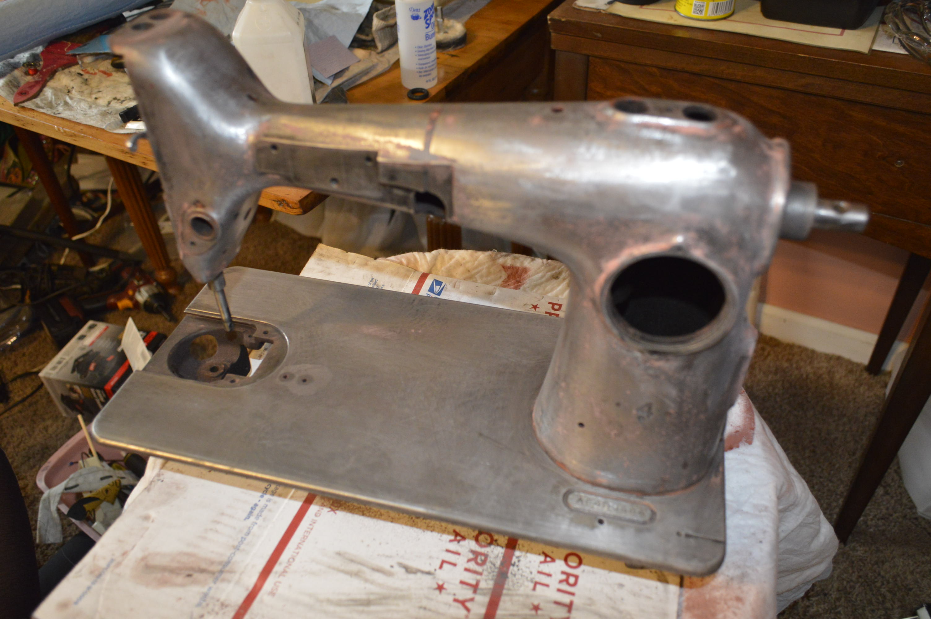
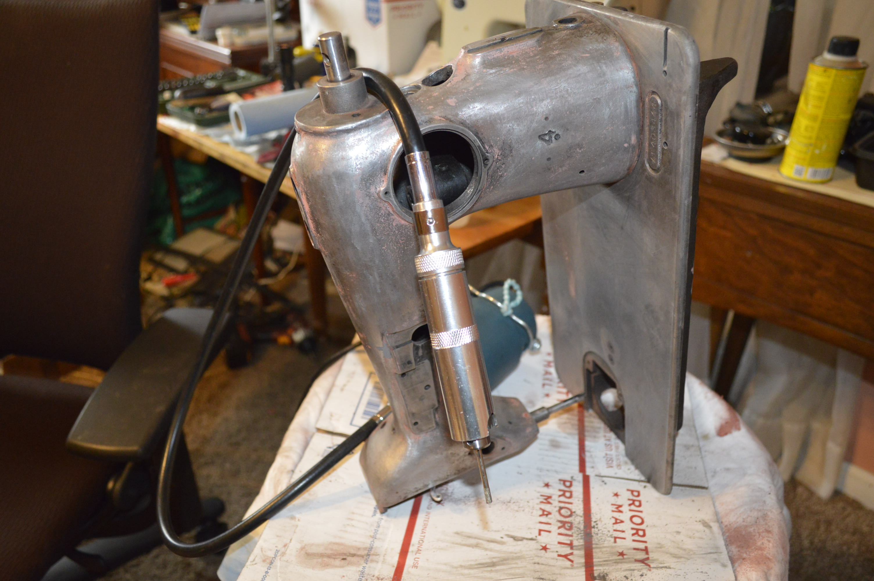
To sum up what I started and catch up to the point I started to document the project, it went like this…I removed the finish by sand blasting the body of the machine. In preparation for the sand blasting, I removed everything except for the arm shaft and the drive gear connected to the arm shaft. The motor and balance wheel was removed. The connecting rod, stitch length assembly, and the badge were removed. The gears and gear shaft under the bed were removed, as well as the bobbin case/ hook assembly. The rocker arm assemblies were also removed. Typically, I remove all of the parts in the sewing machine head including the presser bar assembly and the needle bar assembly. The presser foot assembly was removed, but as stated earlier, the needle bar assembly was destined to remain in the machine. What the heck, I figure all singers start their life forged in fire so I couldn’t do worse.
I covered all of the holes with duck tape and sand blasted the body of the machine to bare metal. This served two purposes, it took the machine to bare gray metal, and it evened the finish without damaging it. This makes paint prep easier. After the machine was sand blasted, I dipped the machine in a vat of kerosene heated to 145 degrees until the body of the machine reached 145 degrees and then let it cool in the kerosene until it reached the ambient outside temperature (you guessed it, my wife won’t let me do this in the house). After the machine was removed from the kerosene, it was power washed with water inside and out. It was then placed in a vat of water with a small amount of detergent and again heated to 145 degrees until the body of the machine was 145 degrees. Instead of letting the machine cool with the water, the machine was removed from the water hot. Because the temperature of the machine was 145 degrees, the water flash evaporates before any rust can form. I then used compressed air inside and out to remove any remnant of sand blast media, I sprayed inside of the arm shaft with WD-40 (for a word on using WD-40, see my topic on oils to use and oils to avoid under the “tips and tricks” menu), waited a bit, and again use compressed air inside and out. Finally, I oiled the arm shaft and arm shaft bushing liberally. The paint remaining on the body (protected by the duck tape) was removed with 100 grit sandpaper. Now I am caught up.

I covered all of the holes with duck tape and sand blasted the body of the machine to bare metal. This served two purposes, it took the machine to bare gray metal, and it evened the finish without damaging it. This makes paint prep easier. After the machine was sand blasted, I dipped the machine in a vat of kerosene heated to 145 degrees until the body of the machine reached 145 degrees and then let it cool in the kerosene until it reached the ambient outside temperature (you guessed it, my wife won’t let me do this in the house). After the machine was removed from the kerosene, it was power washed with water inside and out. It was then placed in a vat of water with a small amount of detergent and again heated to 145 degrees until the body of the machine was 145 degrees. Instead of letting the machine cool with the water, the machine was removed from the water hot. Because the temperature of the machine was 145 degrees, the water flash evaporates before any rust can form. I then used compressed air inside and out to remove any remnant of sand blast media, I sprayed inside of the arm shaft with WD-40 (for a word on using WD-40, see my topic on oils to use and oils to avoid under the “tips and tricks” menu), waited a bit, and again use compressed air inside and out. Finally, I oiled the arm shaft and arm shaft bushing liberally. The paint remaining on the body (protected by the duck tape) was removed with 100 grit sandpater. Now I am caught up.
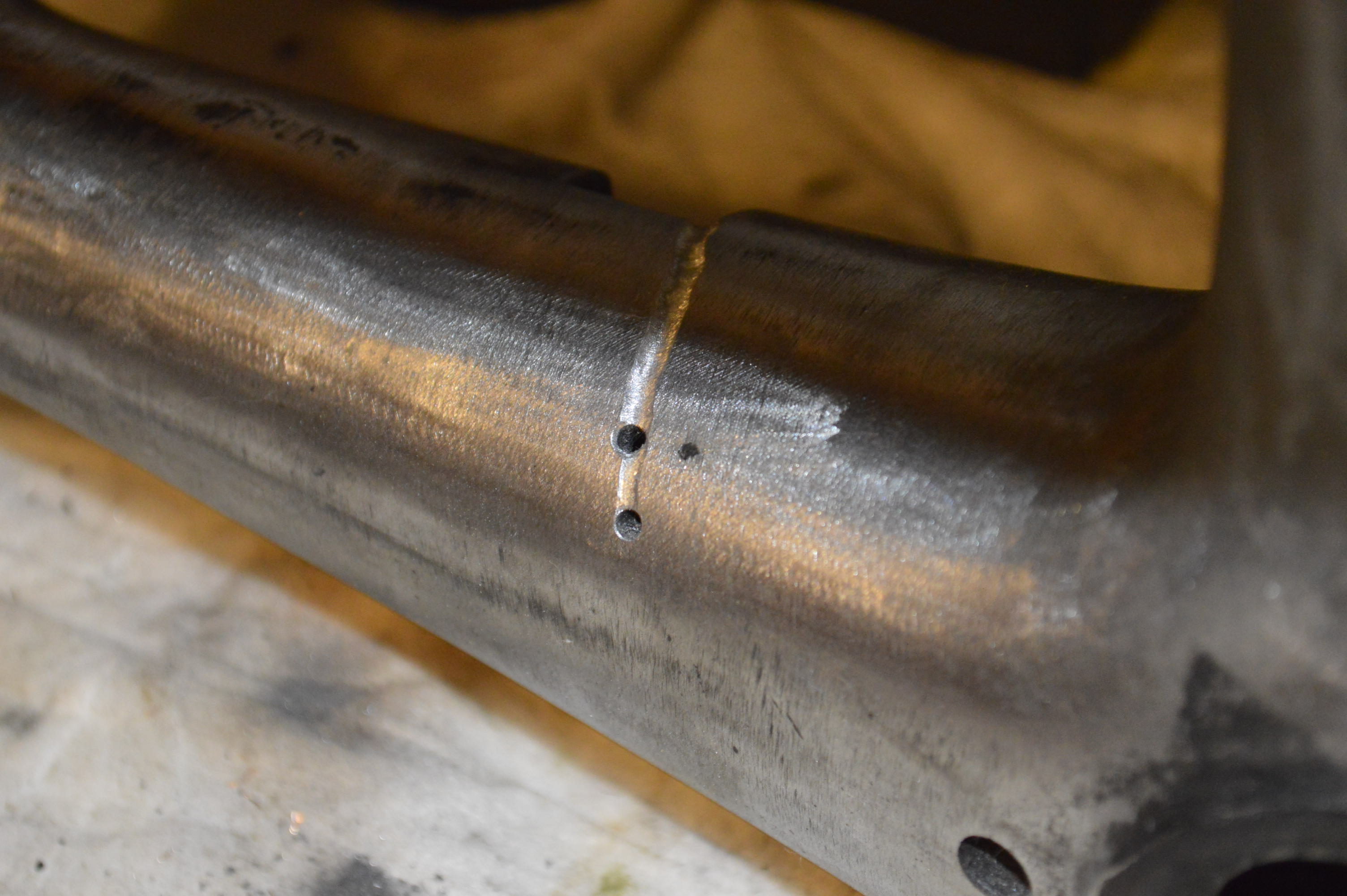
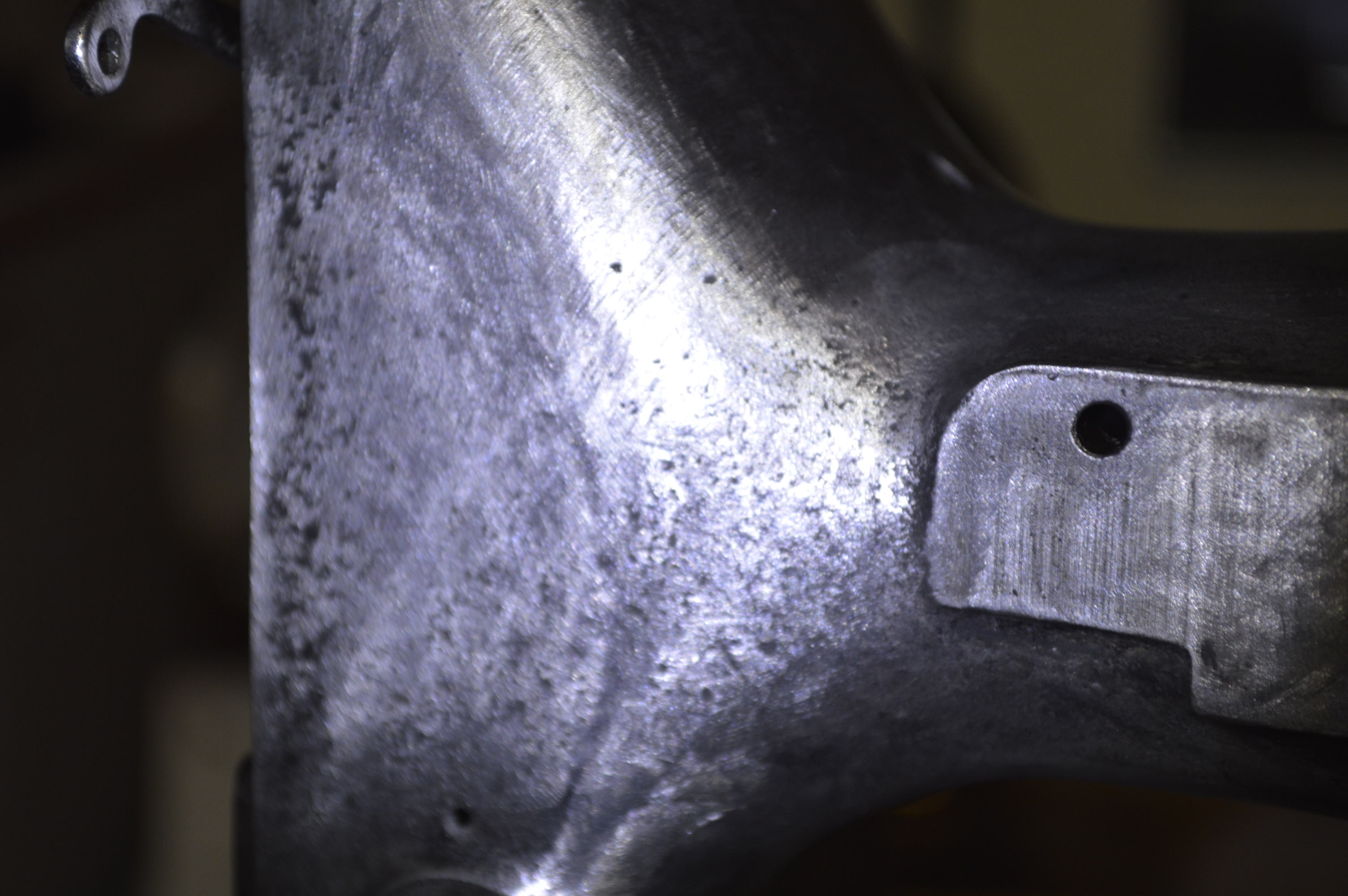
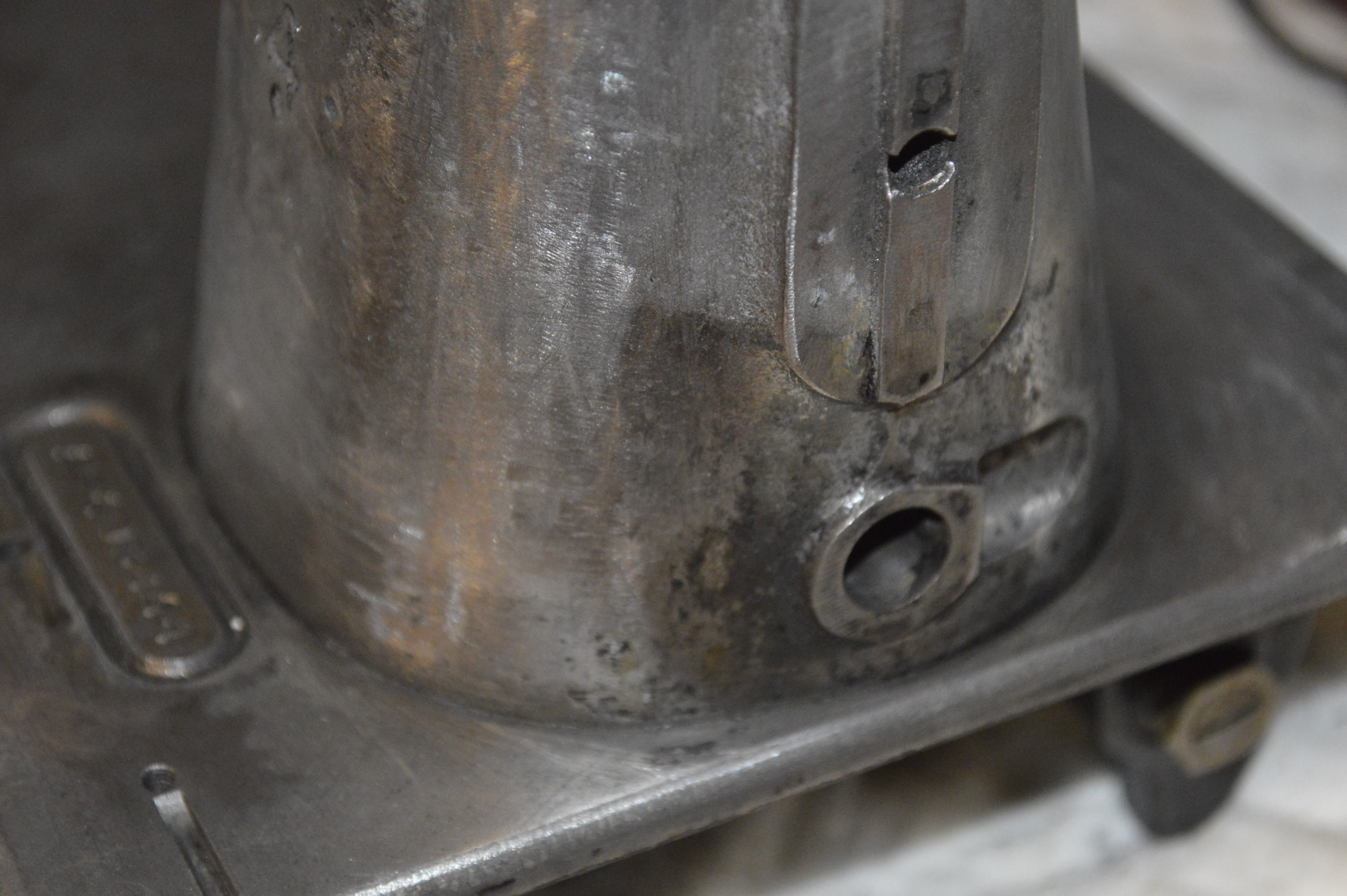
That’s when I noticed the crack… actually 2 of them. They were tightly closed cracks on the sewing machine arm, and I can’t tell you how it happened. Well, I’m turning back now. In my younger days, I was a welder apprentice, and then certified welder in the Naval Shipyard. I know from experience that there is only one way to repair cast iron and that is to braze it, (No… I’m not going to get into a discussion by many that say they weld cast iron with welding rods. While there are welding rods designed to do the job, I have never seen any really good results). Either process, if used requires the piece to be heated to at least 500 degrees. After the brazing (welding) is done, the temperature is much higher. To prevent the cast iron from cracking when it cools down, it must be cooled slowly and in a controlled fashion. I can tell you that this ain’t going to happen on a sewing machine. I believe that the bushings and tight tolerance shaft would be damaged by the warping that would inevitably result in the repair. My only feasible SAFE option was JB Weld 2 part epoxy. I’m moving on.
If you noticed, there are holes drilled at the end of the crack. These holes will prevent the crack from growing any further. The crack was routed out with a carbide bit in a dremel drill.
The groove was filled with JB weld…
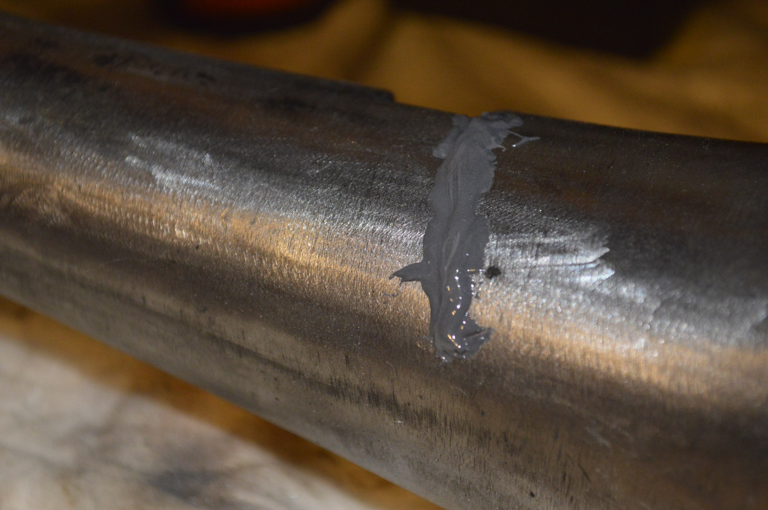

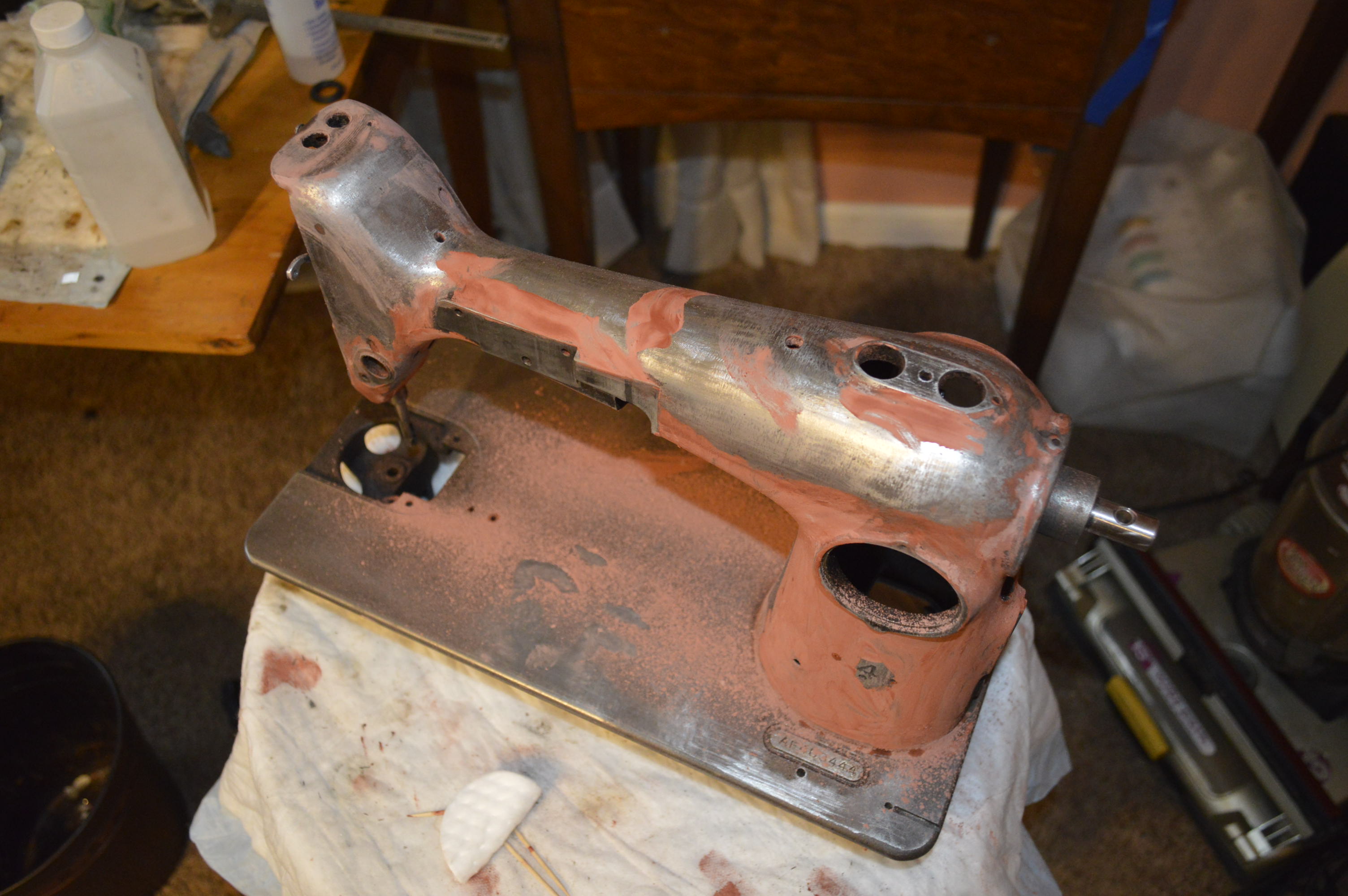
After curing for 24 hours, the JB weld was contoured flat… One thing that is readily noticeable is all of the casting defects in the body casting. You don’t have to do anything with these, but for a restoration, I want a smooth finish, so these defects just won’t do.
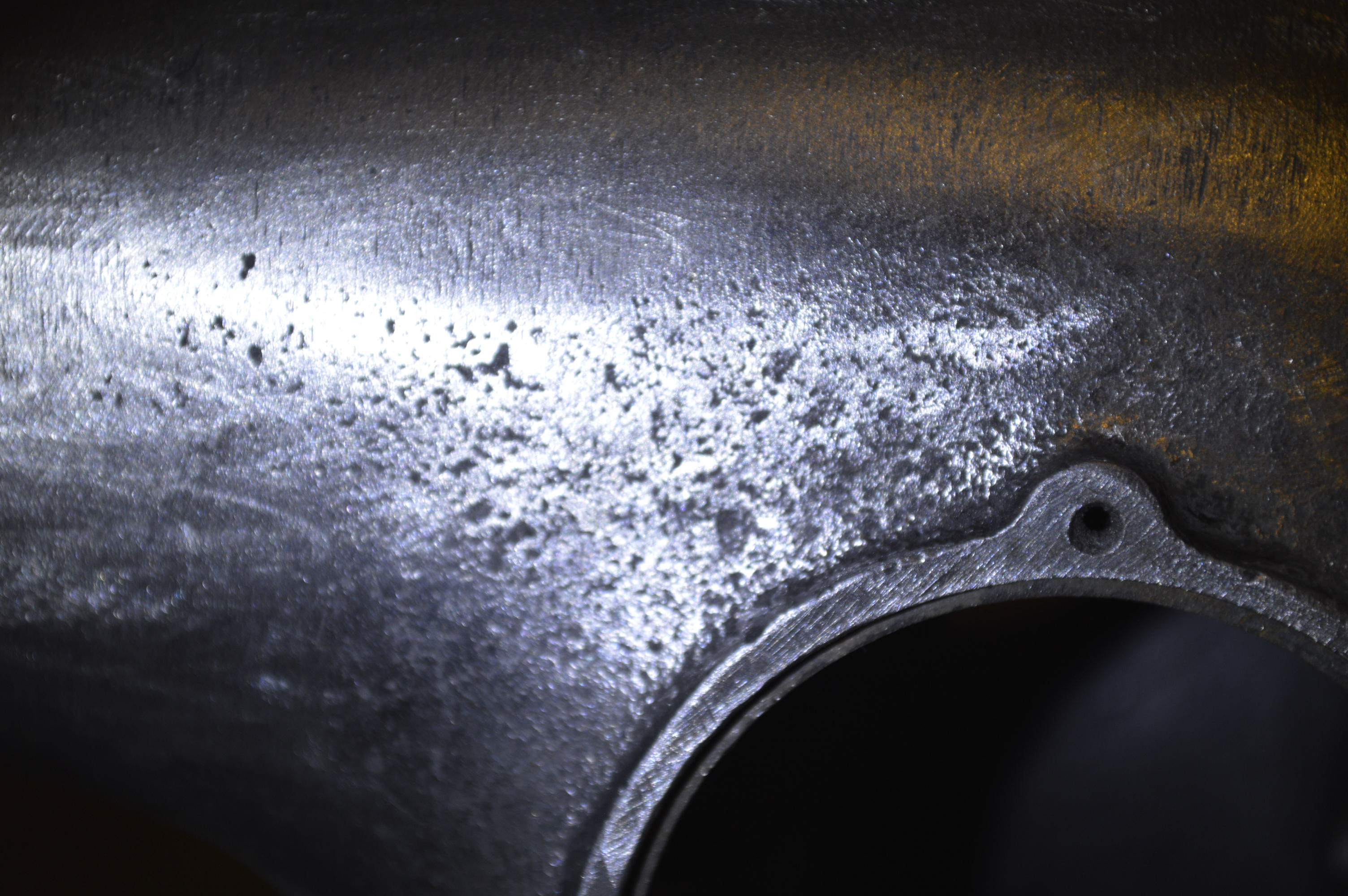
Next step in the process is to cover the body with body filler glazing compound. All of this will be sanded off and the pits will be filled flush with the surface.
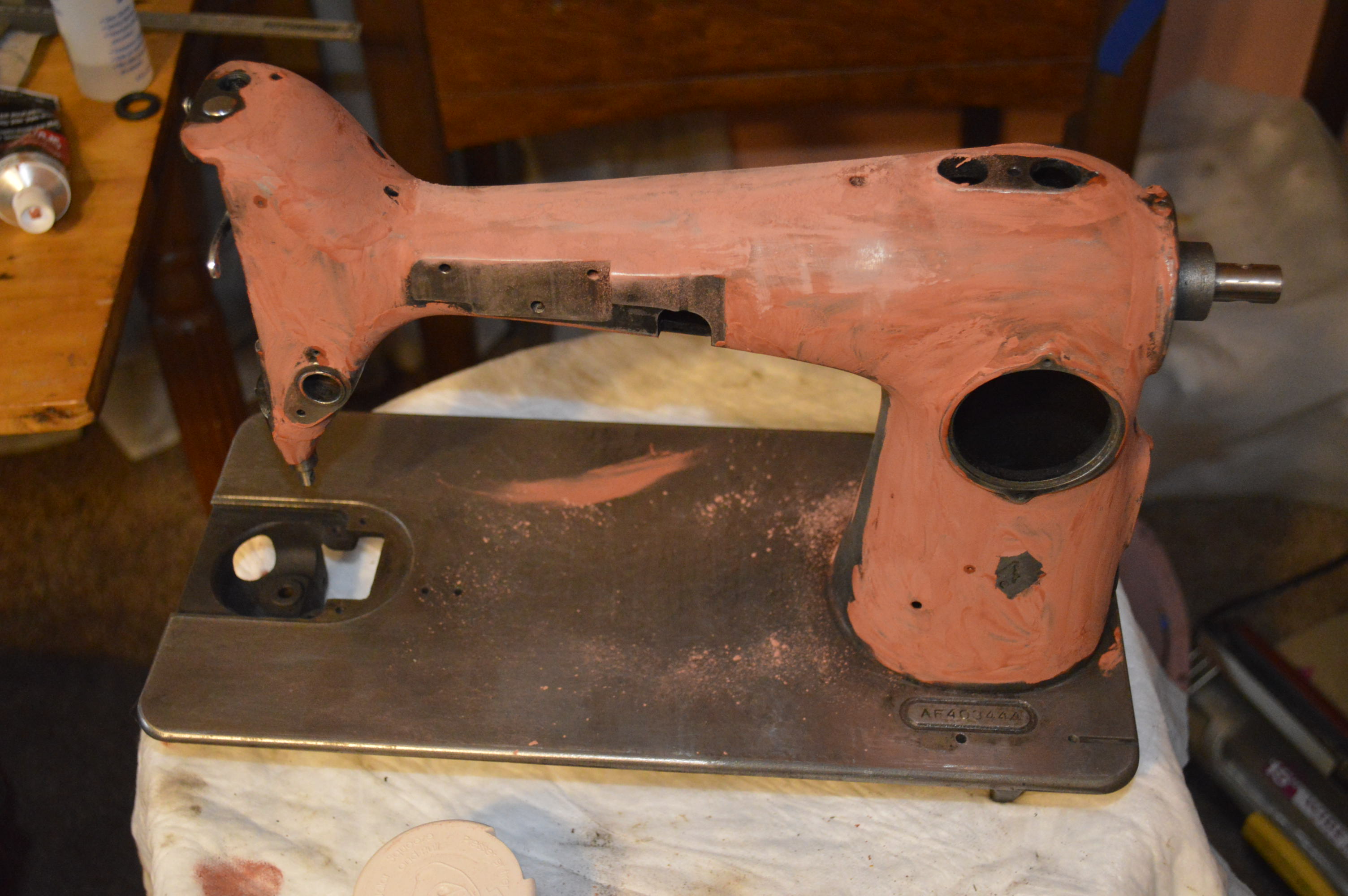
After sanding, it looks pretty much like it did, except for now it is smooth.

I noticed a seam on the back of the machine where the casting line was exposed, so it was contoured with the dremel, and glazed to fill the rough surface.
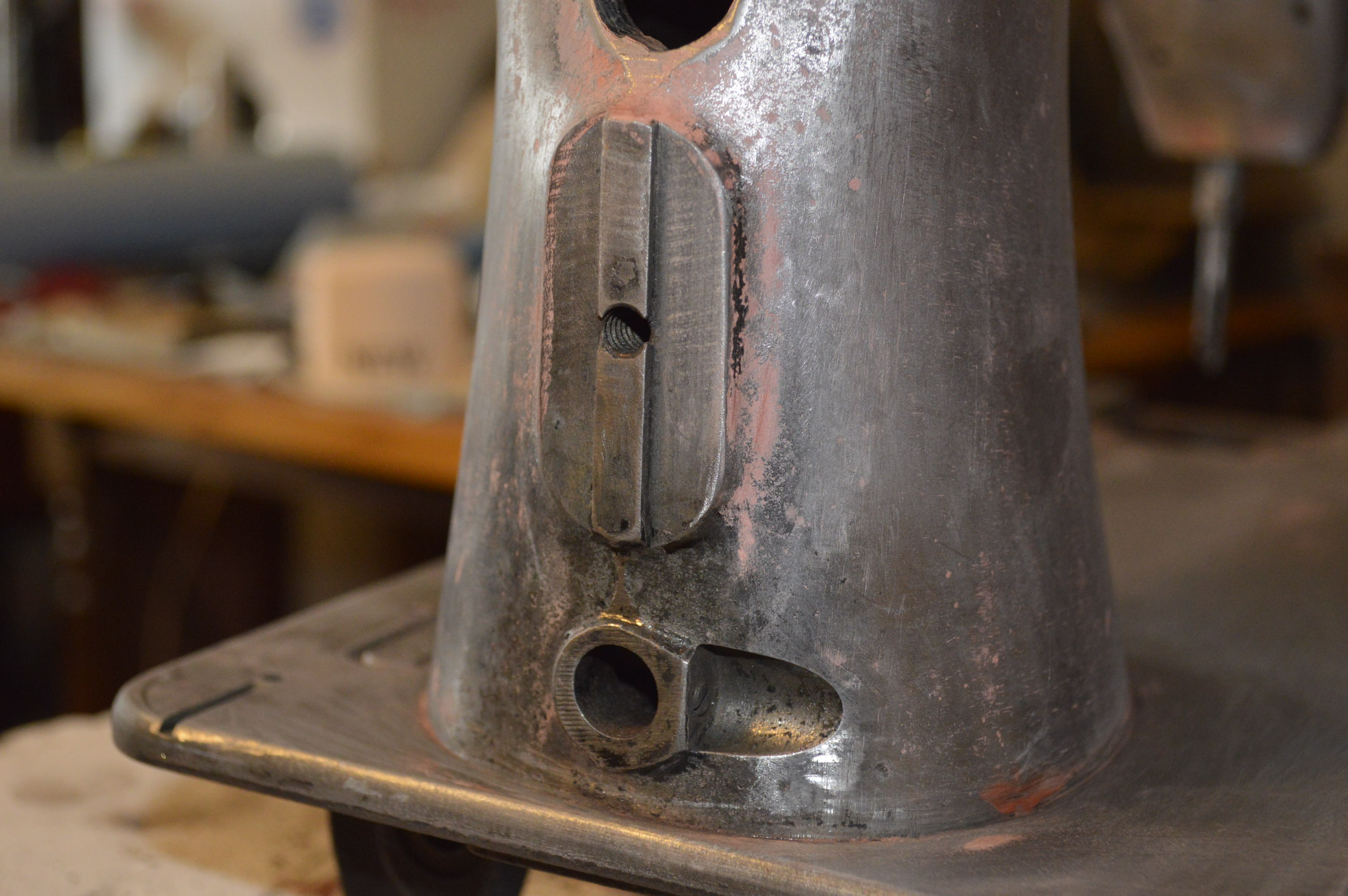
Seam Ground Flat
A final sanding over the entire surface of the machine with 150 grit sandpaper and the machine is ready for masking, priming,and painting.
The machine is coated with 3 coats of white primer, allowing adequate drying time between coats. Each coat of primer is followed by wet sanding with 600 grit sandpaper for a smooth primed surface ready for paint.
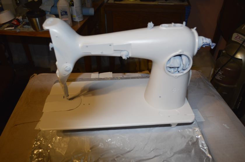
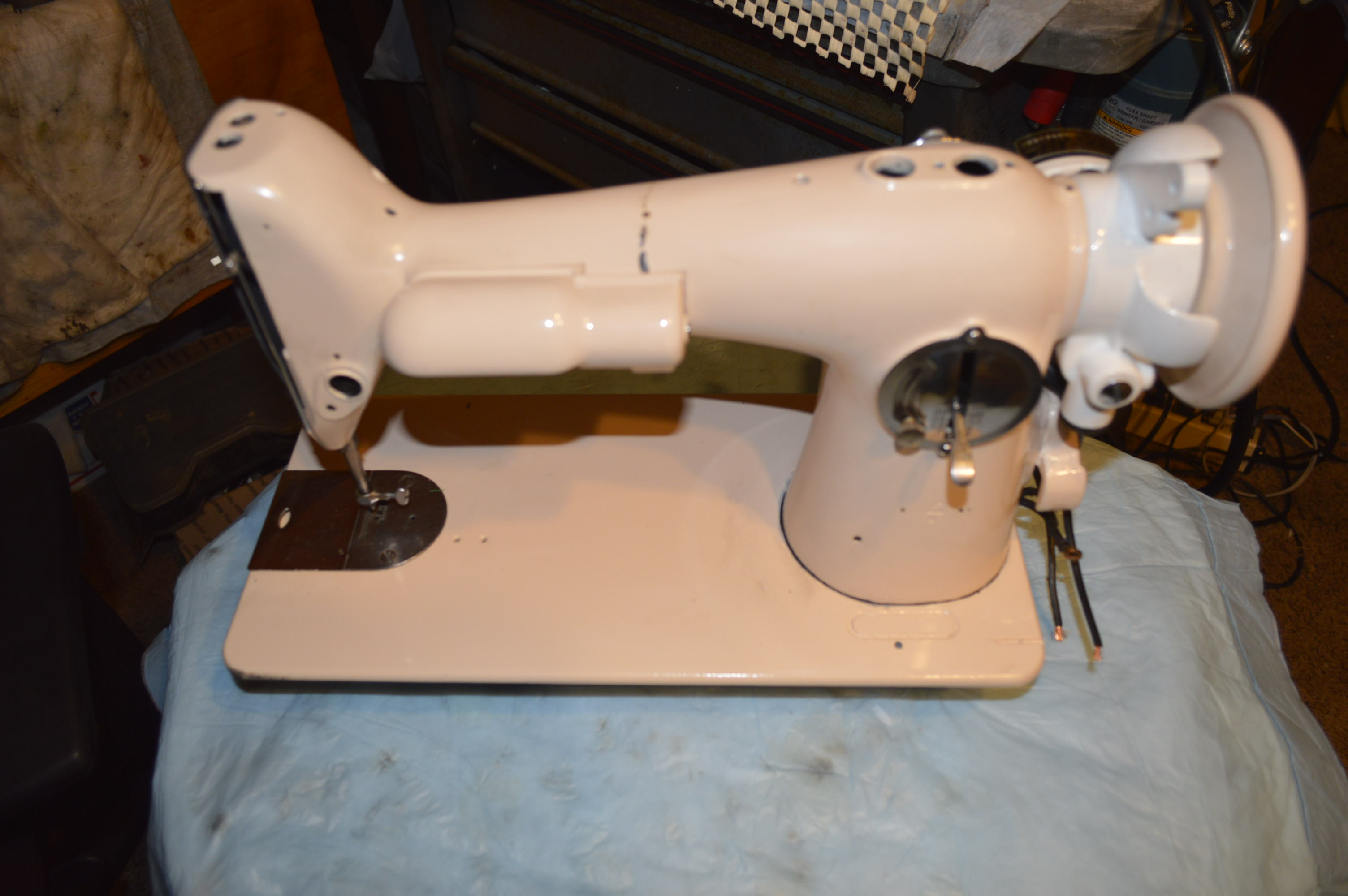
The first coat of paint is applied and allowed to dry for 24 hours before wet sanding… 3 coats will be applied for a deep smooth color… my Wife chose “Pink Peoney”.
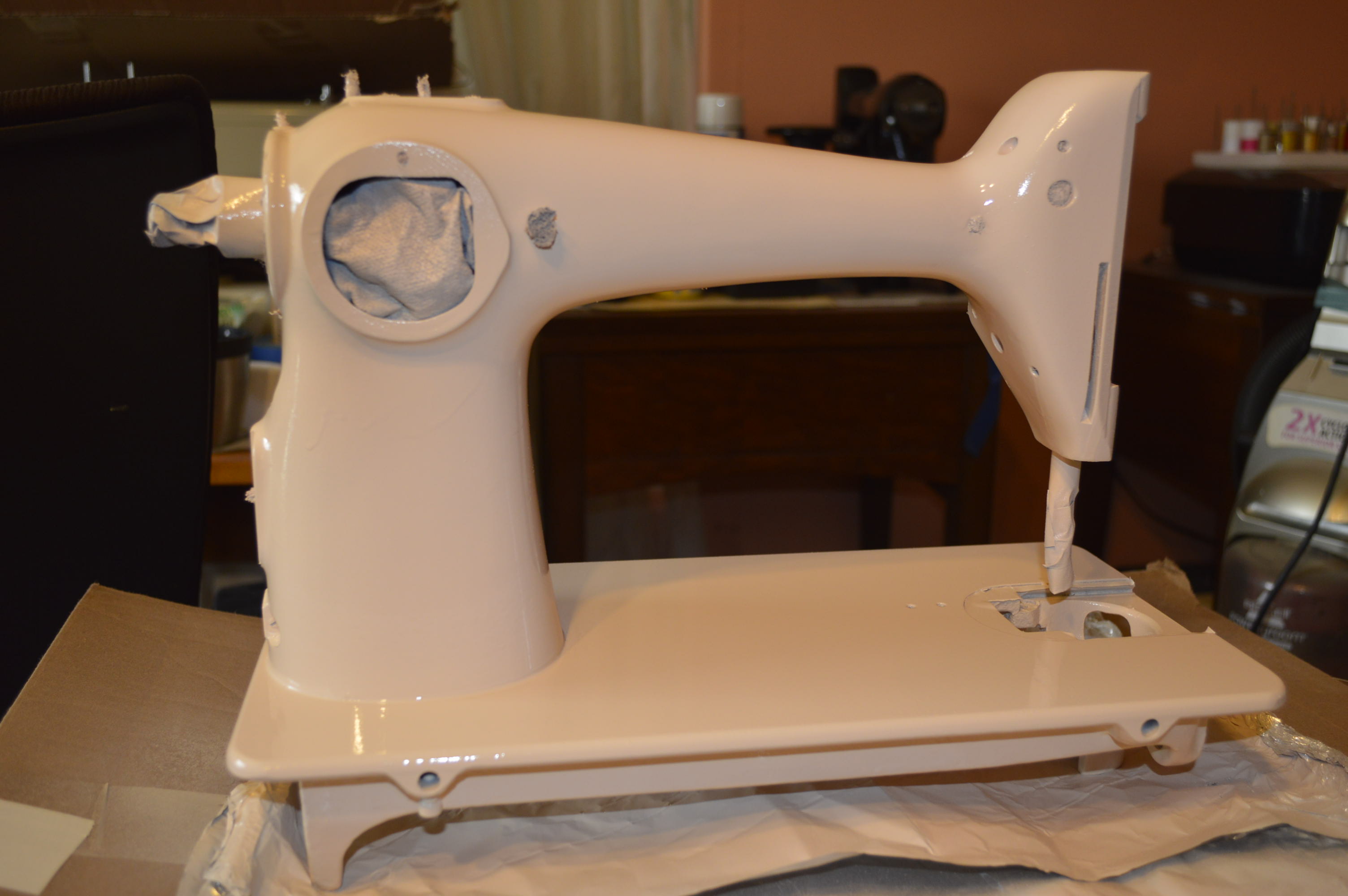
Well, that’s where the project is today. I’ll continue with the project over the next few weeks to complete the paint, reassemble the machine, apply restoration decals, top coat, and final polishing.
The machine has had 3 coats of peony pink, followed by wet sanding with 600 grit sandpaper. The final sanding was only enough to remove the smallest defects. The machine was wrapped in a plastic bag and set aside. It will cure for about 2 weeks before applying decals… What to do now? Time to get to the motor.
Dissasembly is pretty straight forward:
- Remove the wires from the back of the terminal block. The terminals are marked 1, 2, and 3. Make a diagram to show what wire goes to what terminal (motor, controller, and light). The digram is also easily found on the internet.
- Remove the balance wheel.
- Remove the motor from the machine. The screws holding it on are VERY tight. You will need a proper fitting screw driver and then tap (not HARD) on the end of the screw driver as you are trying to loosen the screw. This impact will unseat the screw and it will come out easily. Do not try to remove them using a screw driver alone. Unless the motor has been removed before, you will certainly ruin the screw heads.
- Remove the cap screw on the end opposite the motor cover.
- Remove the two large screws from the bottom of the motor. These are the grease wick caps.
- Carefully remove the motor brush caps. You will see them on opposite sides of the motor. One on top, one on the bottom. Use a tight fitting screwdriver. These caps are brittle and can be broken easily.
- Remove the brush springs (hopefully with the brush attached). If the spring pops off of the brush leaving the brush still in the housing, don’t worry, you can push them thru after the armature is removed.
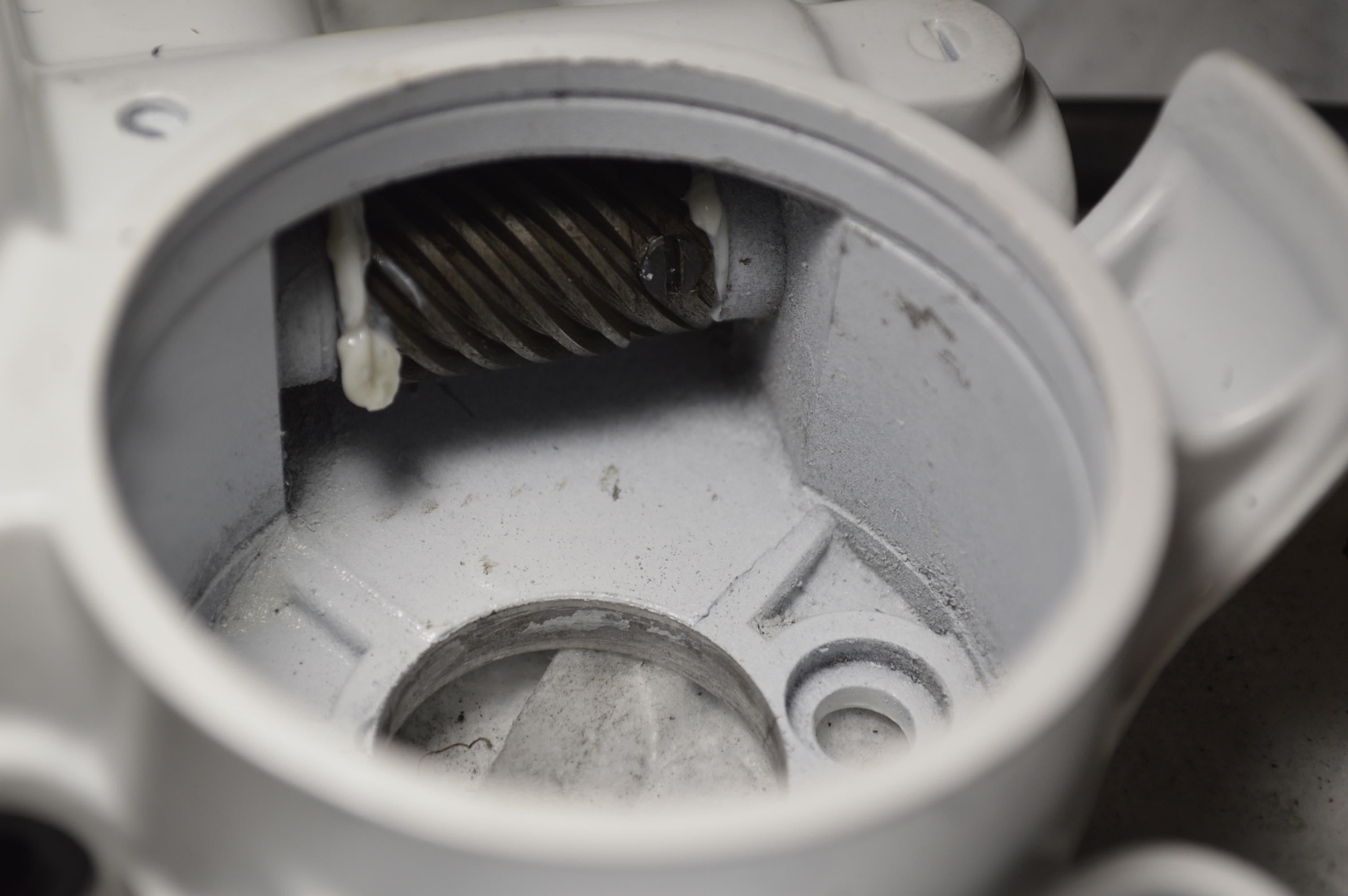
- Inside the motor housing, you will see a spiral gear and lots of old grease. On the end of this gear (farthest from the winding) there are 2 small screws set flush with the gear. You will need to rotate the armature to see both of them. Loosen these screws… you don’t need to remove them.
- Gently remove the armature from the housing Look for a thin washer, it is either on the armature shaft or still in the motor housing. Don’t lose this, it will need to be installed for the servicing to be successful.
- Remove the 2 screws holding the field coil to the housing. You will need to gently pry up on bottom of the coil. The coil will pop up. You will not be able to pull the coil any farther than the wires connecting the brush holder, but you will have enough room to remove the power lead wire to replace and solder.
- There are many detailed instructions on the internet and videos on youtube. I strongly recommend you read and watch how the wires are replaced.
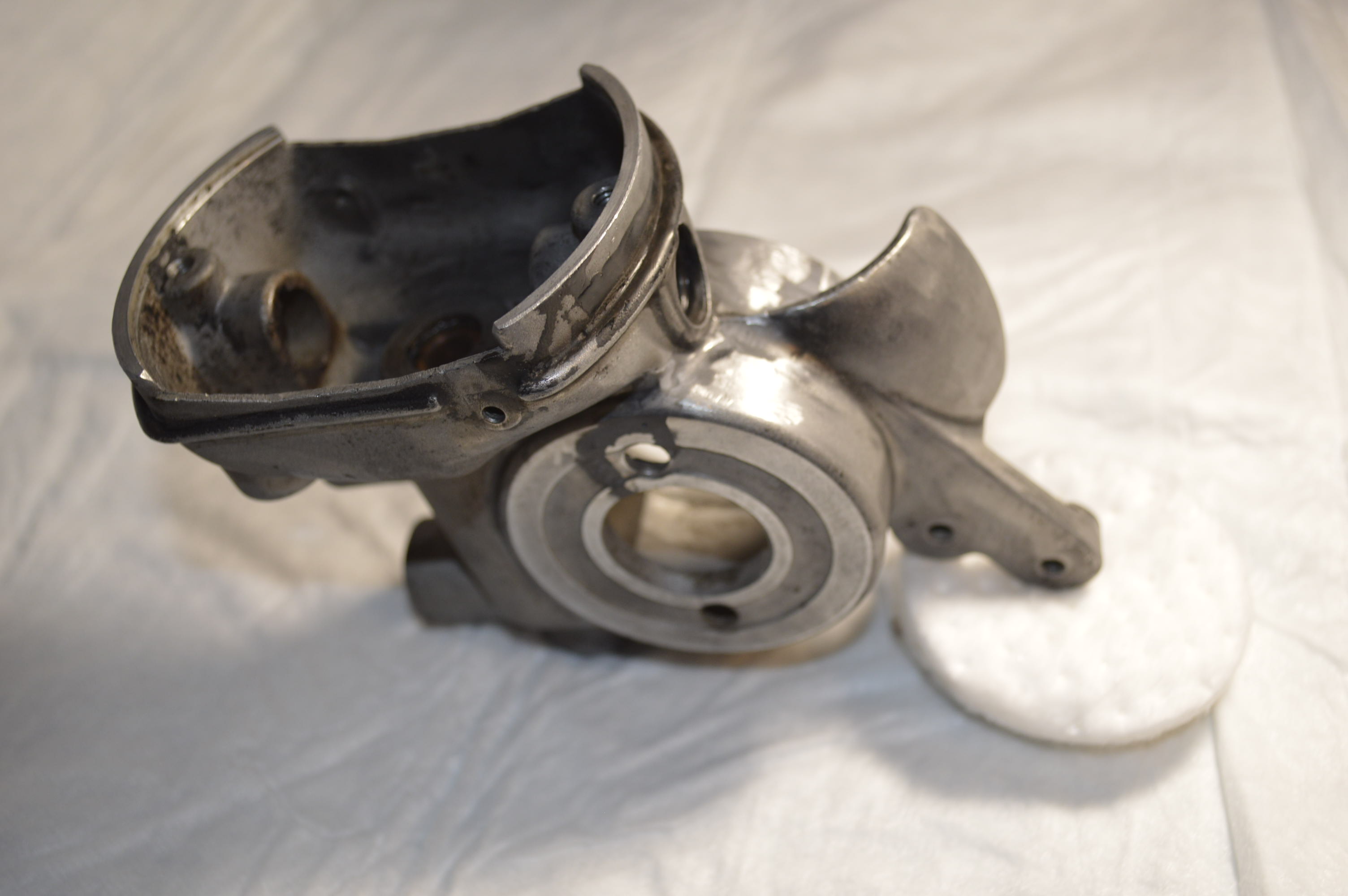
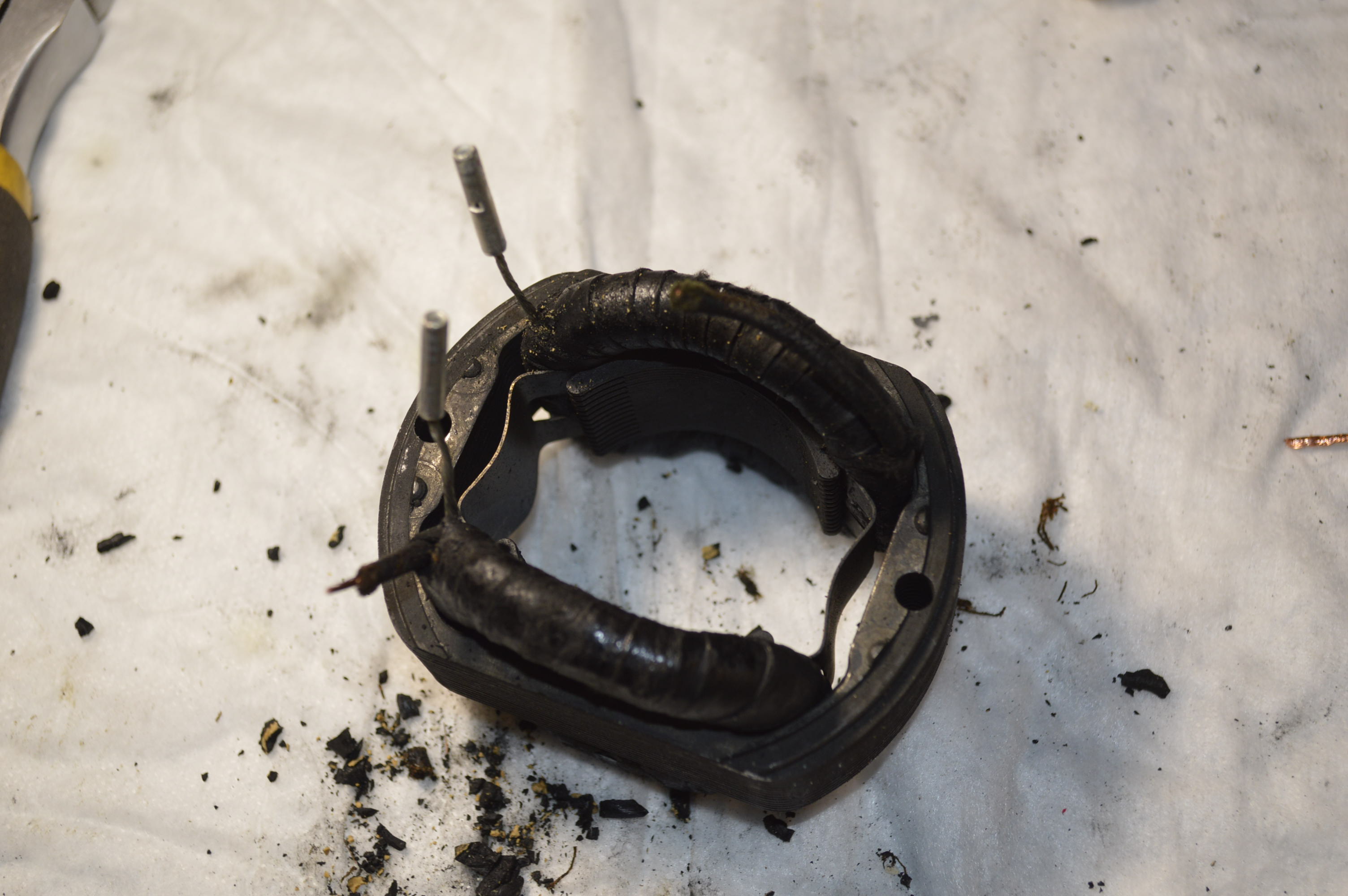
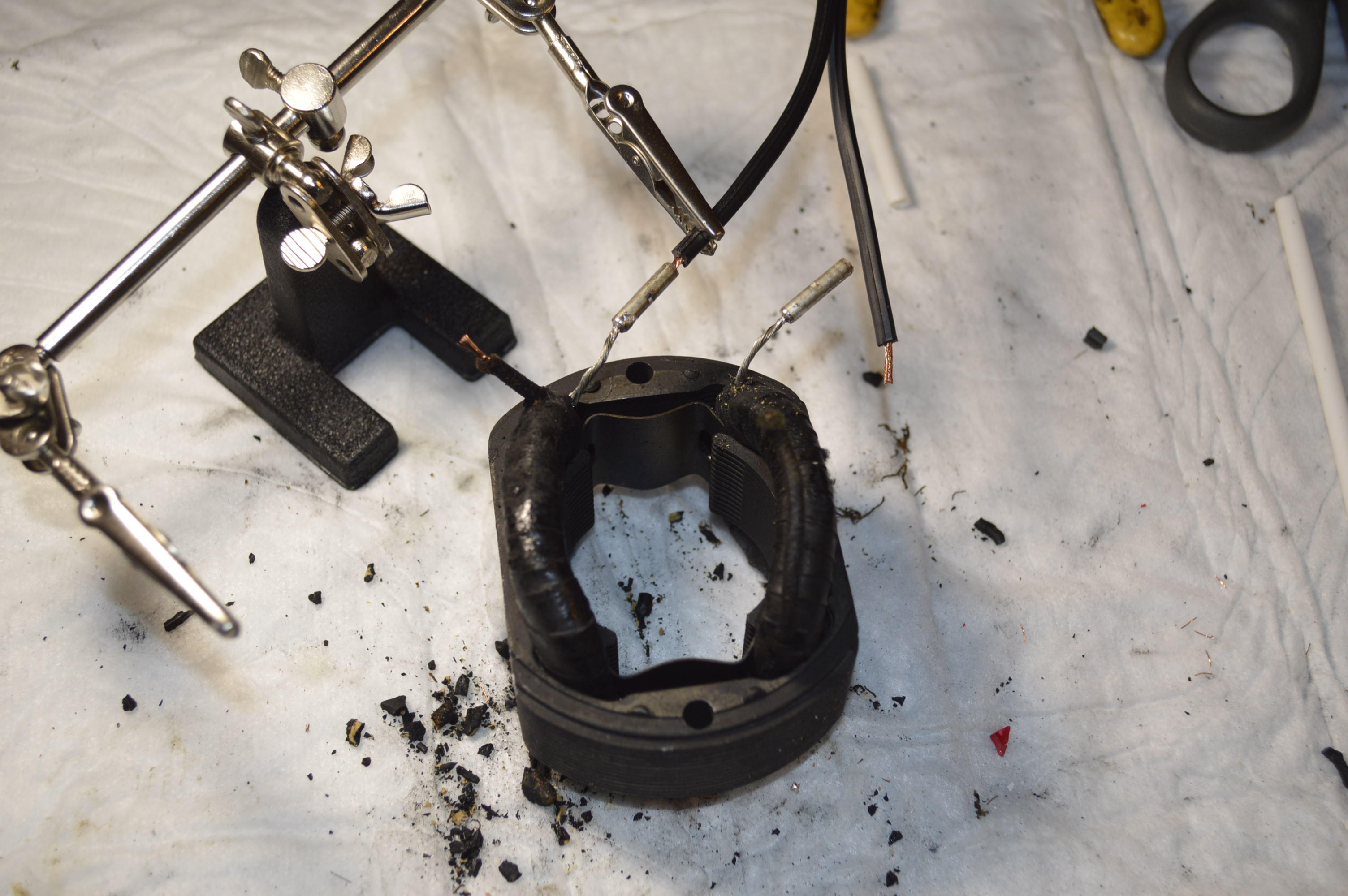
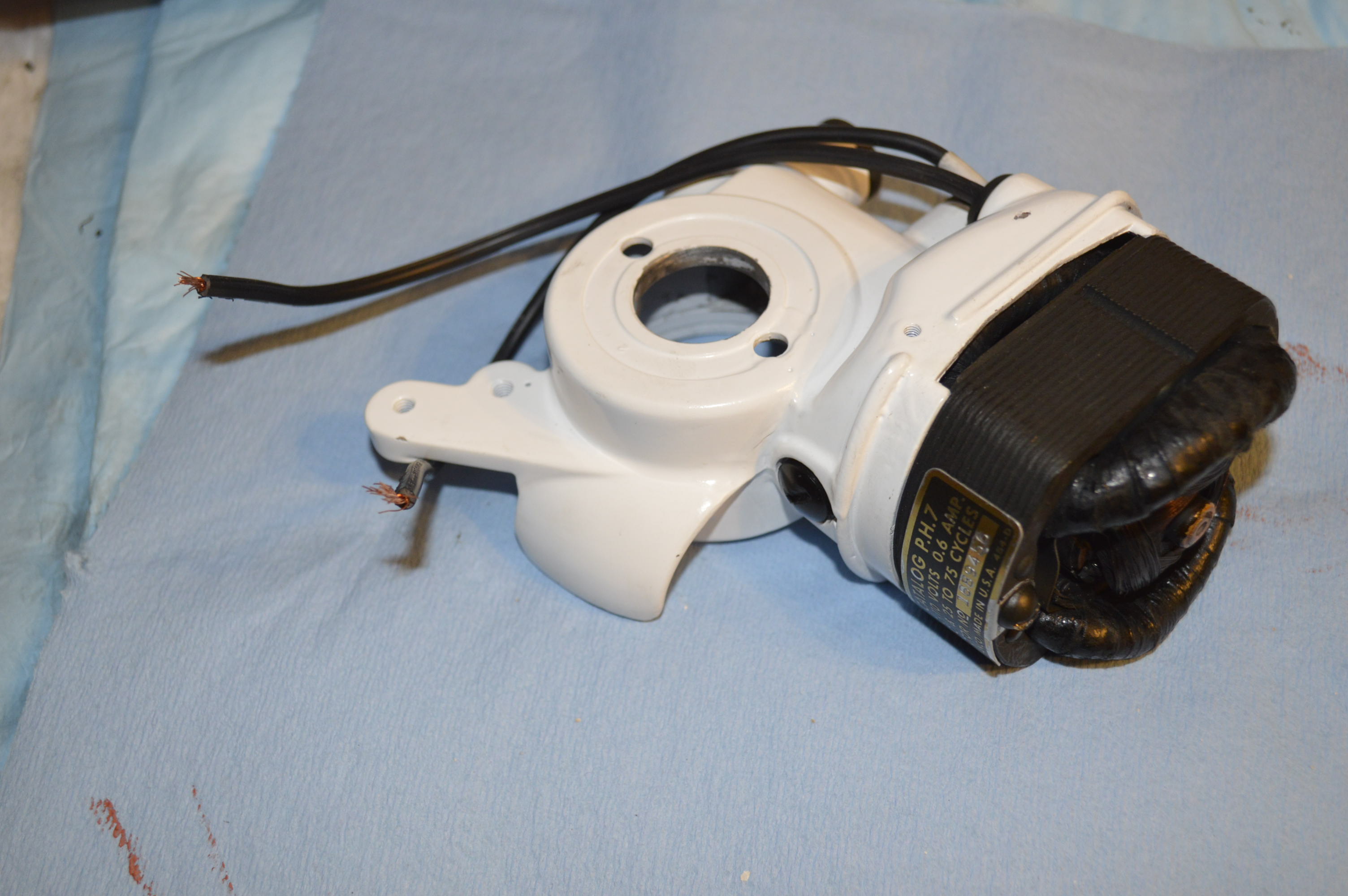
I disassembled the motor and was expecting that the normal motor servicing would be adequate… boy was I wrong! The motor was in pretty bad shape and the motor housing was cracked. Normally, I would replace the motor at this point, but then we wouldn’t learn anything! The motor bits after disassembly looks like this:
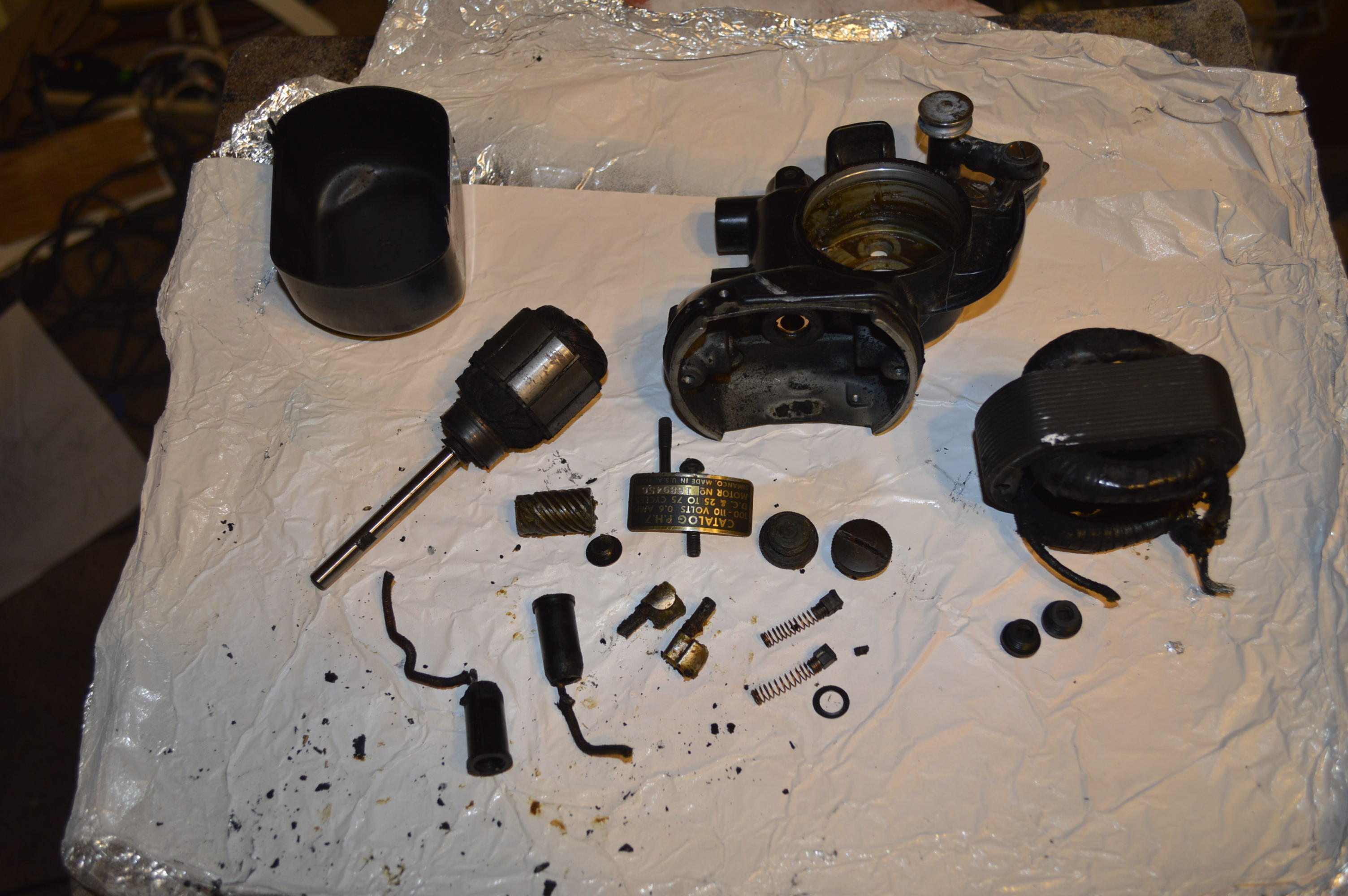
Motor Completely Disassembled
There are a couple of things I want to point out in this picture so if you go this far into the motor you’ll have an easier time with your motor. The first is the small washer shown just below the brushes… make sure this doesn’t get lost. it slides on the armature shaft closest to the commutator and keeps lubricant away from the windings. You may not see this when the armature is removed, but its there… held onto the bushing by grease. Make sure you find and remove it. Notice that the brush holder wires are cut. These are VERY brittle and must be gently pushed out of the motor from the inside, otherwise, the top edge of the holder will break off and be ruined. Before trying to push these out, there are 2 very small set screws that keep the brush holders in place. Looking into the motor housing, you will see them. Normally, these do not need to be removed to replace the wire leading to the motor, but since this motor housing is cracked, and it’s going to be painted, the housing will be completely stripped of parts. See how short the motor brushes are? They are about 1/3 of the original length and need to be replaced. Notice how short the grease wicks are? They are compressed with hardened grease and need to be replaced. The armature needs to be cleaned with electronics cleaner polished. The field coils are coated with grease and crud and need to be cleaned with electronics cleaner. Aside from this, I expect the motor will run fine when it is reassembled.
IMPORTANT NOTE: Do not clean any motor windings with any solvent except one made specifically for cleaning electronics. The copper wire used in the windings is coated with lacquer to keep them from contacting the other wires in the winding. Alcohol, acetone, carb cleaner, and the like will dissolve this coating and the motor will be ruined. I use CRC QD Electronics Cleaner.
On my motor, I removed the bobbin winder bracket and spool fill finger. I need to do this to repair the crack.
The motor housing openings were masked off and the housing was sandblasted to remove all of the paint.
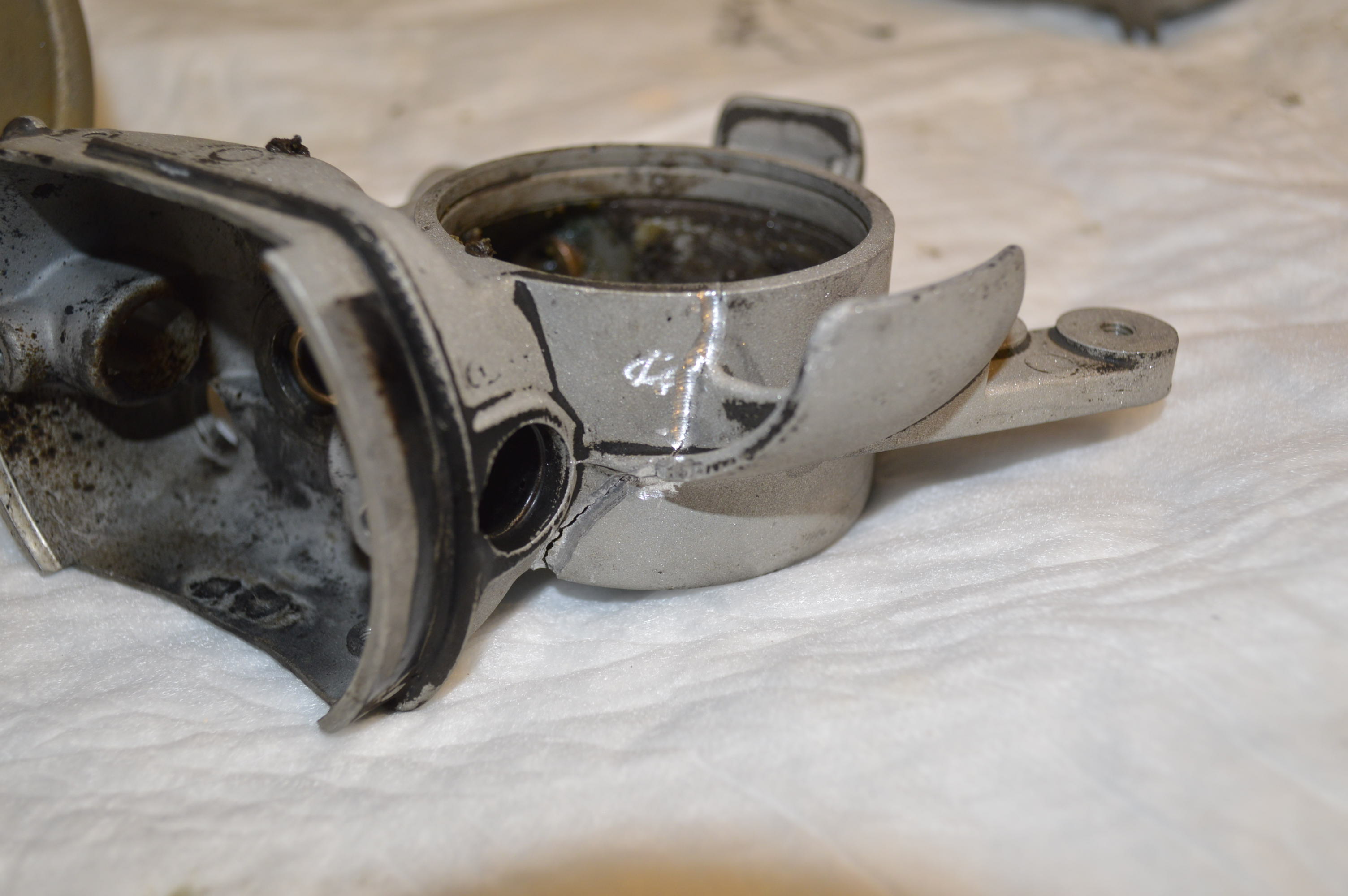
Crack Routed for Epoxy 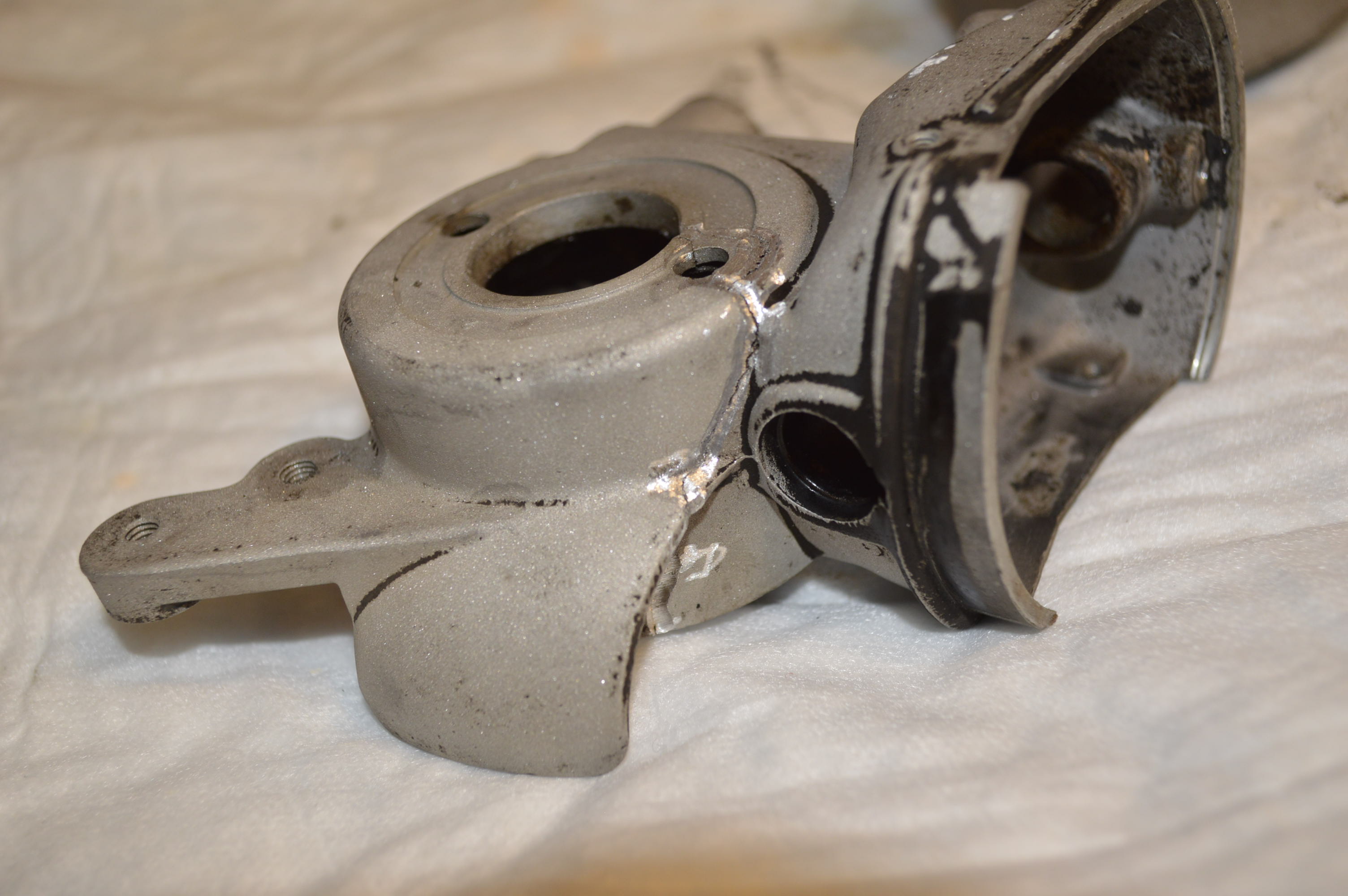
Same on Other side…
You can see where I routed out the crack. The crack was filled with JB weld and left to cure. After curing, the housing will be soaked in kerosene to dissolve the grease. Because the crack extends thru the housing, I will need to rout out the crack and epoxy weld after all of the grease is removed.
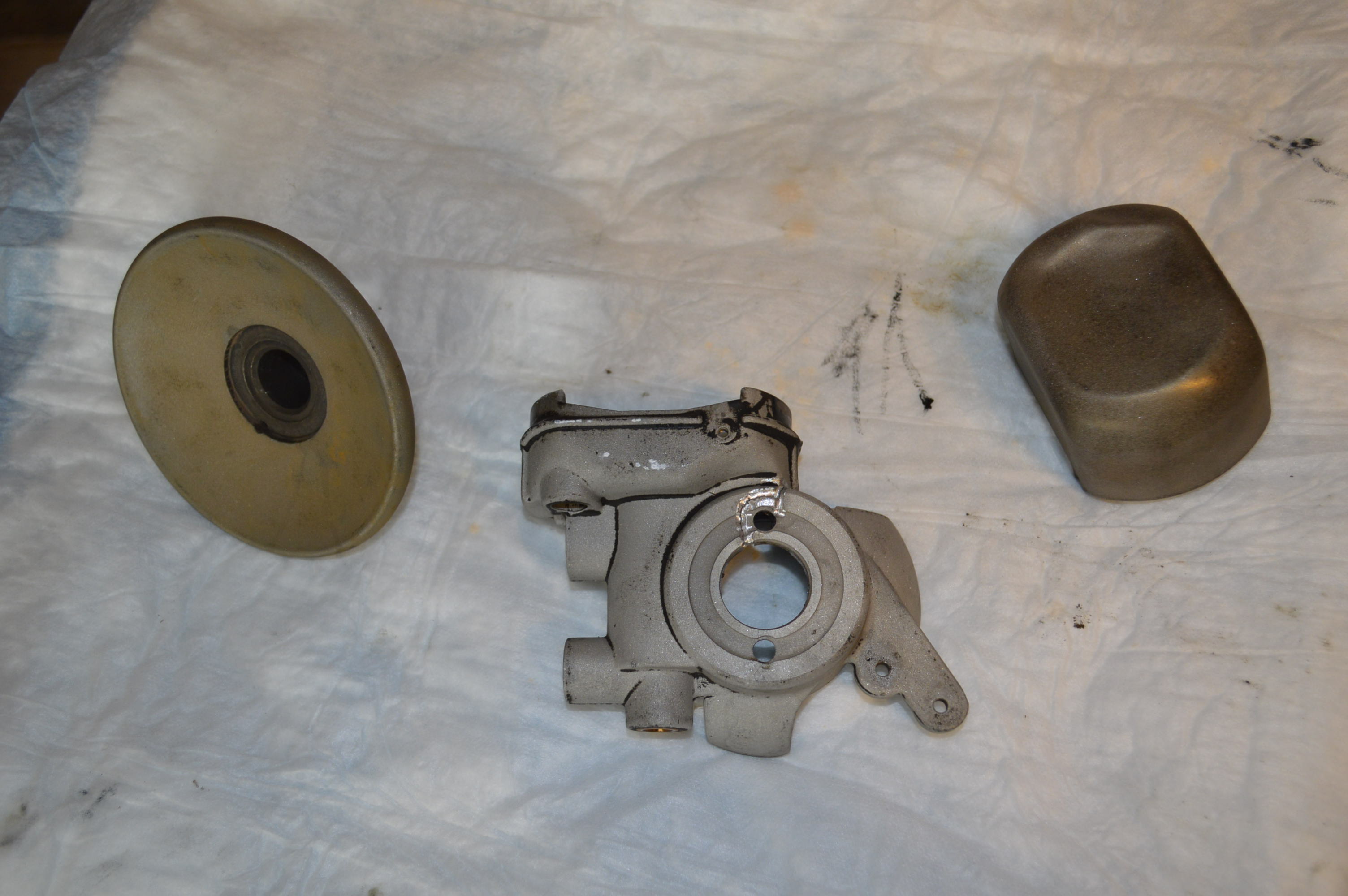
The Balance wheel was masked off and sand blasted, as was the motor cover. I sand blasted these as well. Next step is to prep and paint the motor housing, balance wheel, and motor cover. The motor cover was pretty banged up in shipping, so I will have to straighten it out and fill remaining dents with Bondo. In a normal restoration, I would replace the cover, but for this project, it will be repaired.
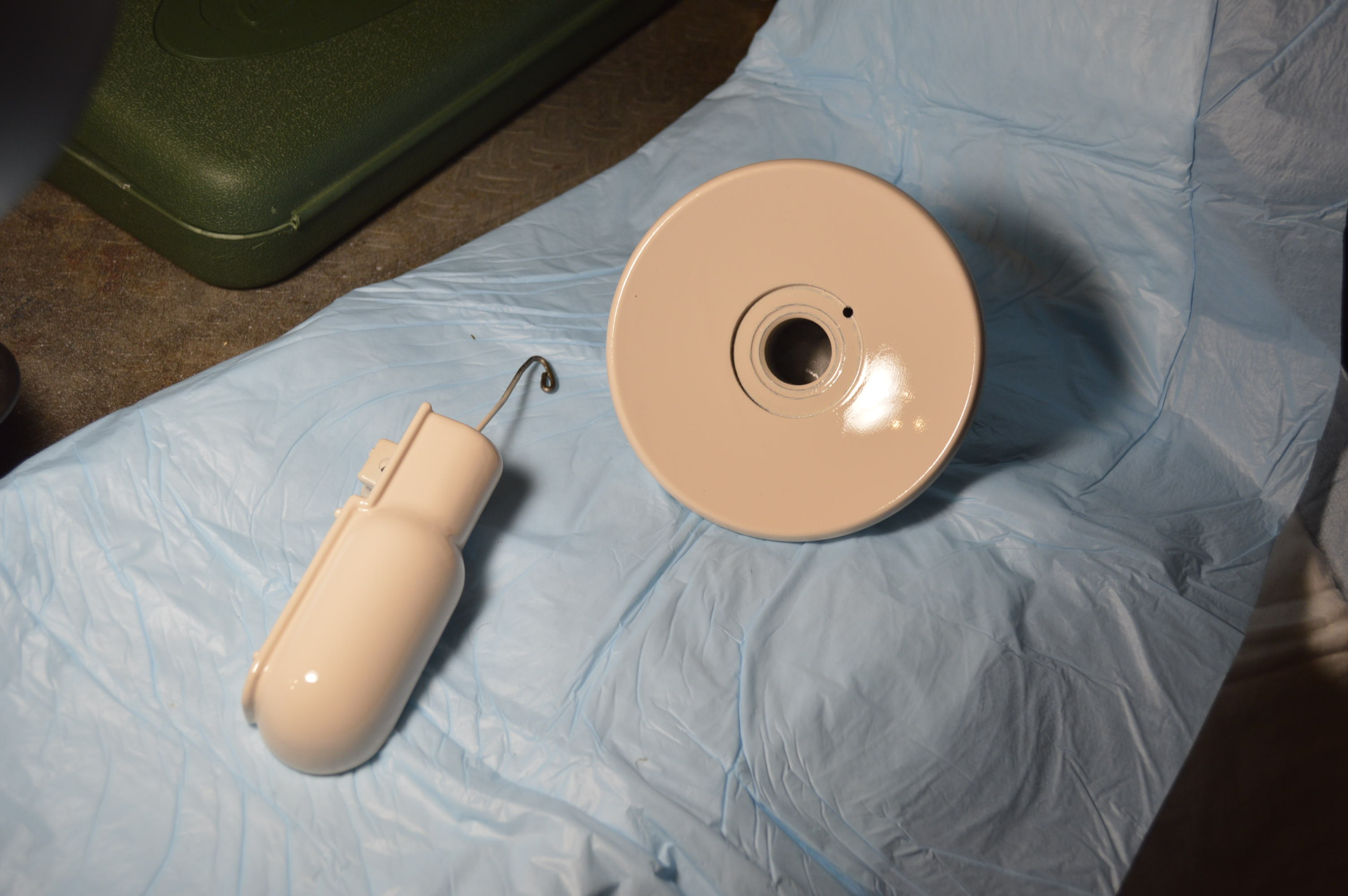
3 coats of primer, 3 coats of paint, wet sand with 600 grit between coats and the balance wheel and light housing are ready for final touch up smooth sanding and clear coat… this will be done with the rest of the machine.
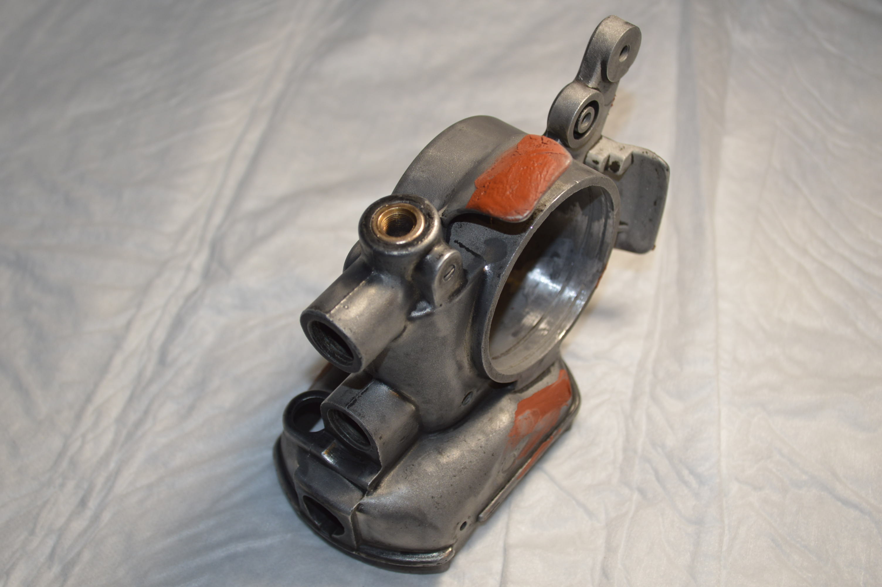
The motor housing has been repaired with JB weld. the repair was contoured. Before proceeding, the entire motor housing was polished with a dremel wire wheel to remove all factory paint in every nook and cranny accessible. To look as good as the rest of then machine at the end of the project, a lot of prep work goes into the motor housing. Remember, details matter so this is the time to get it as perfect as possible.

On this motor housing, I noticed some casting defects that would, or could be visible after painting. Although I could get away with fixing only the defects that are visible from the front, back, and sides, I figure that the amount of work into the project to this point demands that any defect found be fixed.

Casting “Void” Just Left of Center 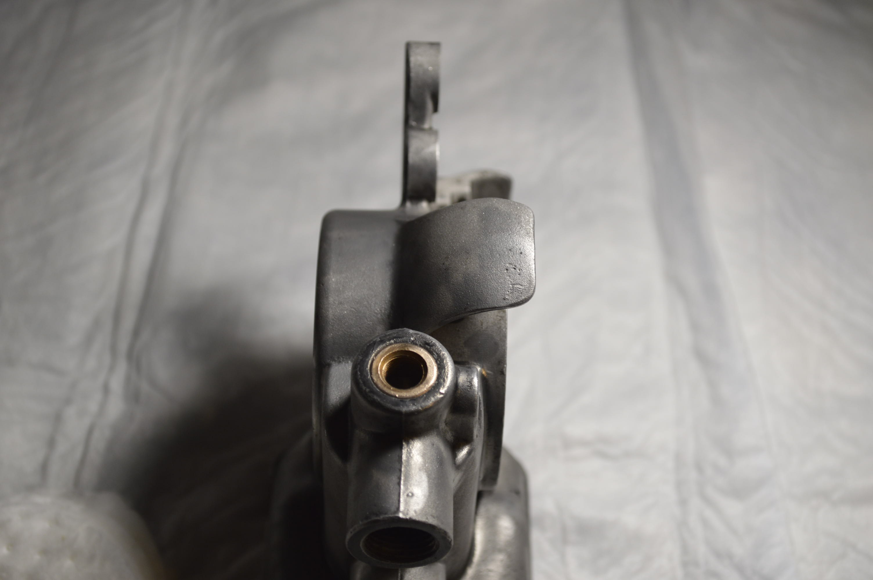
Casting Defects on Bobbin Winder “Wing”
The defects consisted in a small voids in the casting. An application of glazing compound will fill these and be sanded smooth. The housing will be finished by the same process as the rest of the machine. Always keep in mind that for the best paint finish, every detail in the prep work matters.
Glazing Compound Applied Over Defects
Its been a couple of weeks and the paint has had time to cure sufficiently to start thinking about applying decals… We haven’t decided on gold or silver printed 201 decals so I ordered both and will decide when I (my Wife) compares them to the “peony” pink color. Either way, I have another 201 restoration project in the wings and will use the other set on it.
The next step is to put all of the running gear back in the machine. I have spent some time on preparing these parts while all of the painted parts were curing. The painted parts are ready to go back on the machine.
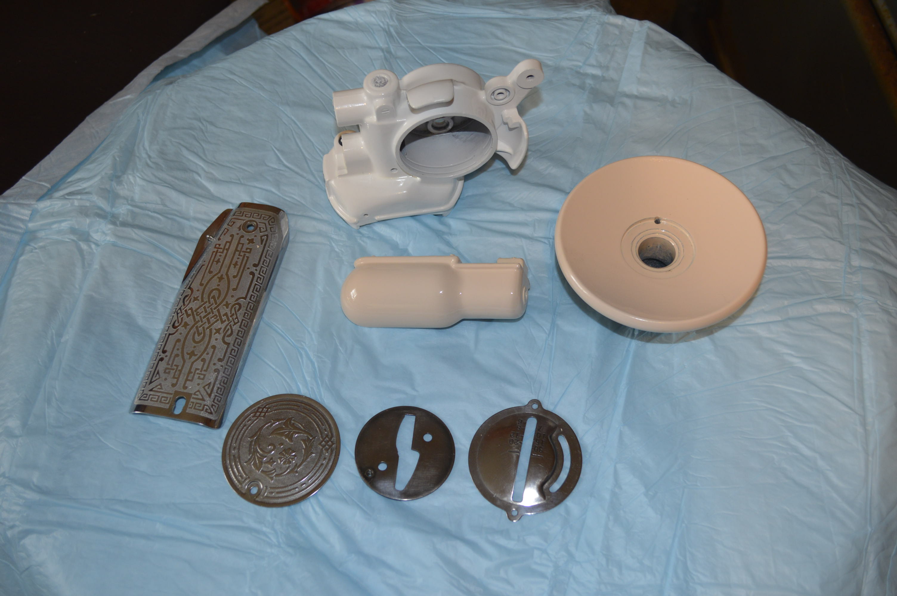
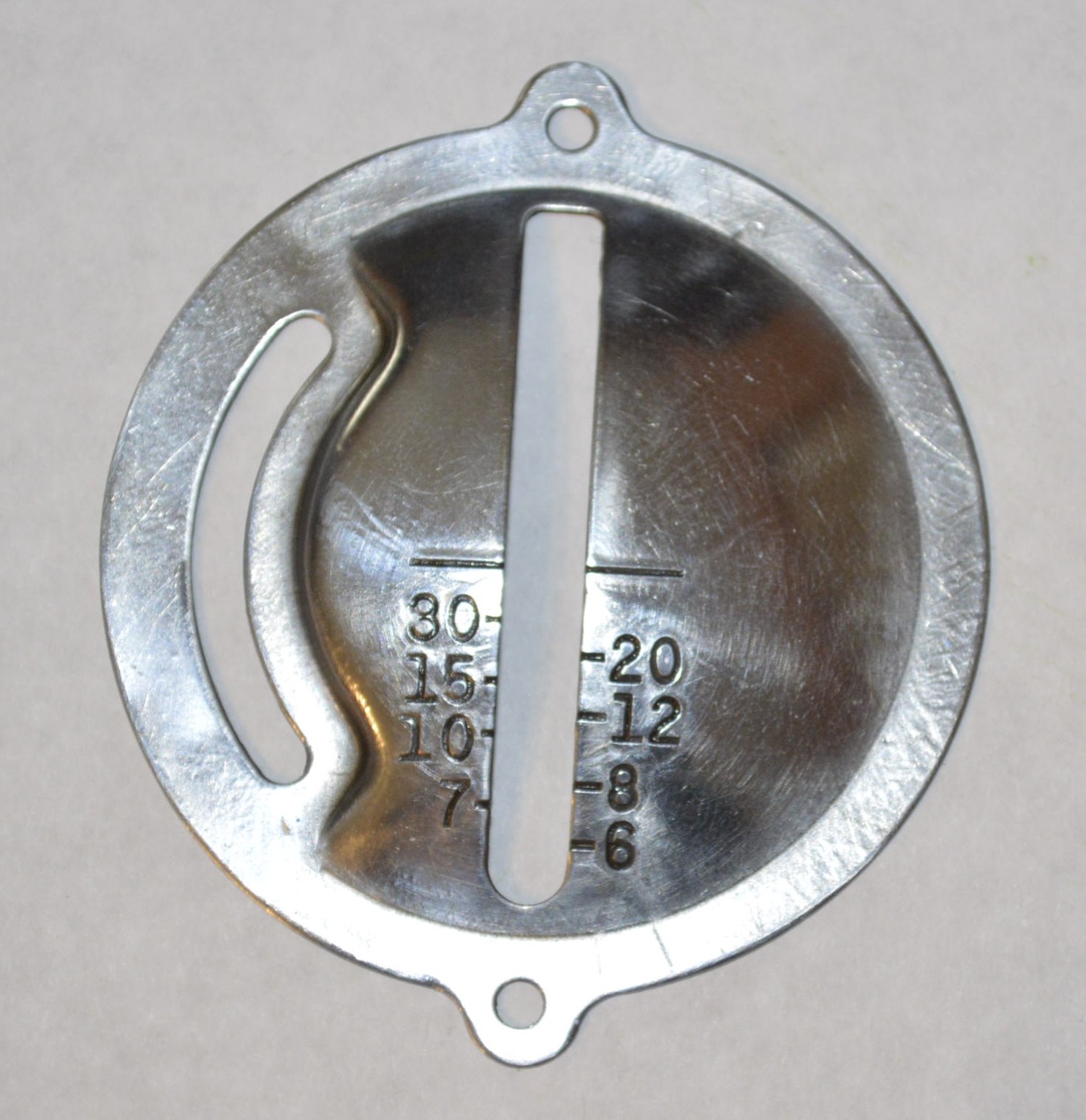
We we not sure what to do with the stitch length cover. Neither the peony pink or white seemed to work the way we thought it would. With so much color, it seemed to disappear in the background of the machine. But, the nickel finish looks great on the cover plates and thought a shiny stitch length cover would look good too…so we stripped the paint from the stitch lever plate and buffed it to a mirror shine. Because this is the color of the steel and not plated, it is protected by clear coat. If we change our minds, we can always change it to a color.
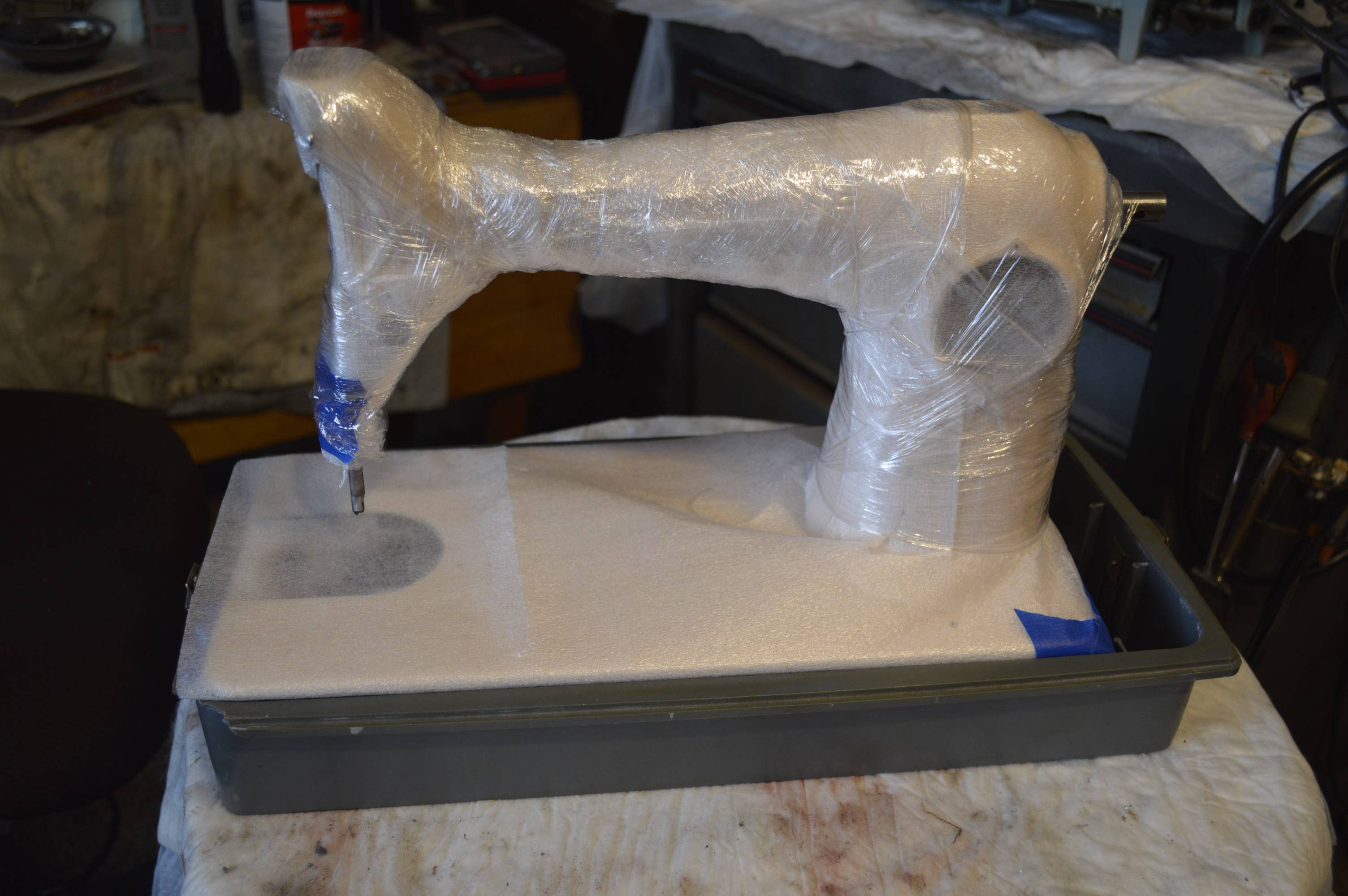
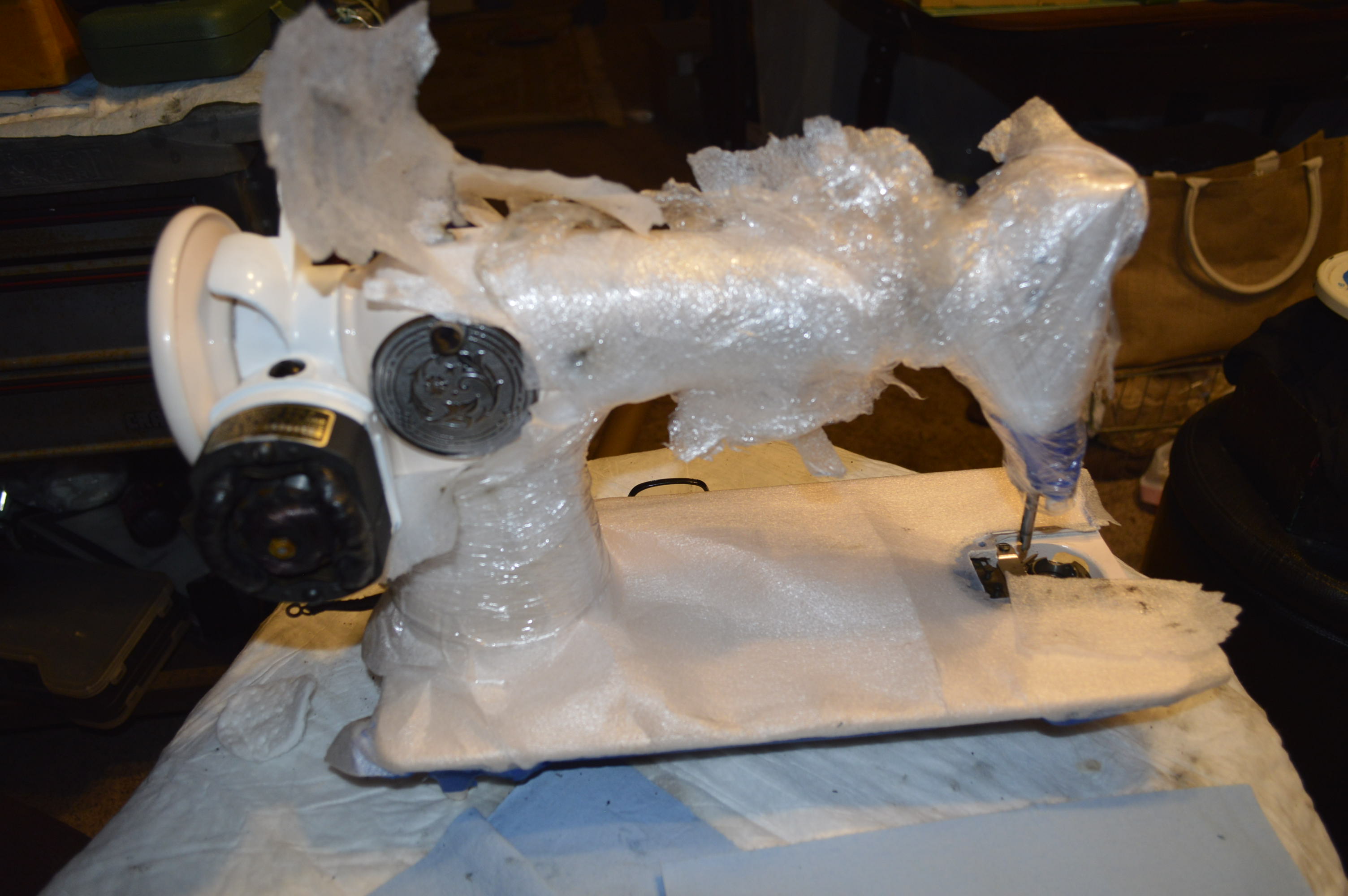
In preparation for putting everything back together, I need to protect the finish from damage. The machine is covered with foam wrapping and cellophane. The machine will need to be handled and flipped side to side and end to end so this will protect the paint from finger prints, lubricants, and any tool marks.
During assembly, the motor will be rebuilt as well. I will breakdown how this is done next.
If you have followed the level of detail in this restoration, you can tell that details matter… Nothing done so far exceeds the detail needed to rebuild a Singer potted motor. They are exceptionally good motors and with the servicing we are doing, it will run great! The achilles heel on these motors is that the wires get brittle with age. I have not come across one of these motors yet that did not have to have the main (field coil) wires replaced. luckily, this is not particularly hard to do if you have ever used a soldering iron before, and there are detailed tutorials on the web to guide you step by step. Unfortunately, I can’t do that with this motor. I will show you what I had to do to get it back to running order! Preparation is the key to success, and here is how I proceeded with the service.


The first step was to clean all of the dust, grime, and old grease/oil off of the armature and coil. I use CRC electronics cleaner because it is safe for the copper motor windings. Remember, DO NOT USE ALCOHOL or ANY solvent cleaner that is not formulated for cleaning electrical components. If you use any of these, the motor will be RUINED and you will end up purchasing another potted motor on online… better yet, get yourself a can of CRC.
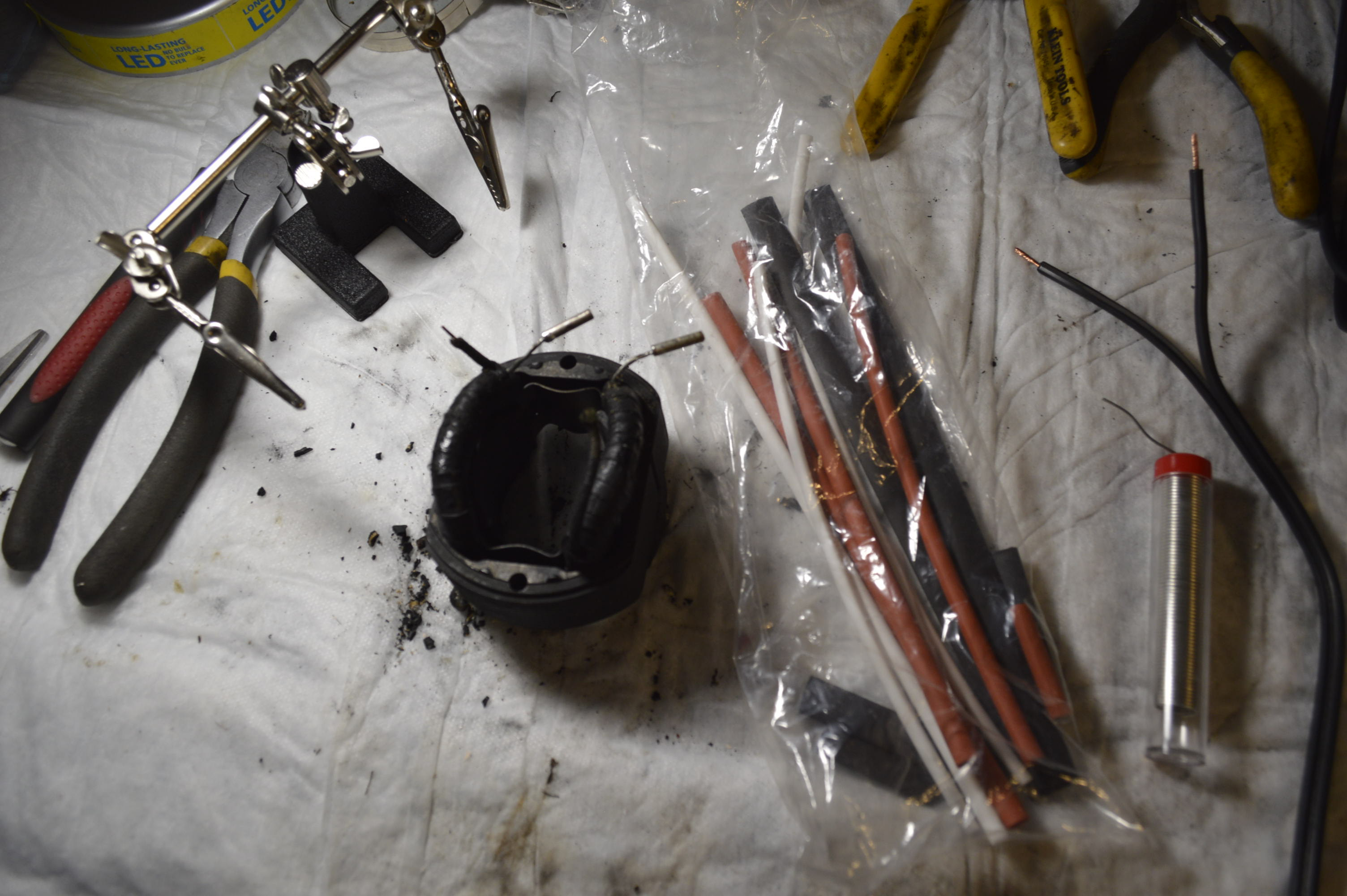
The coil is clean and the wires are stripped back and ready for the new wire. Note the white, black, and red tubes in the plastic bag? That is shrink tubing. We MUST use this, electrical tape won’t work here.
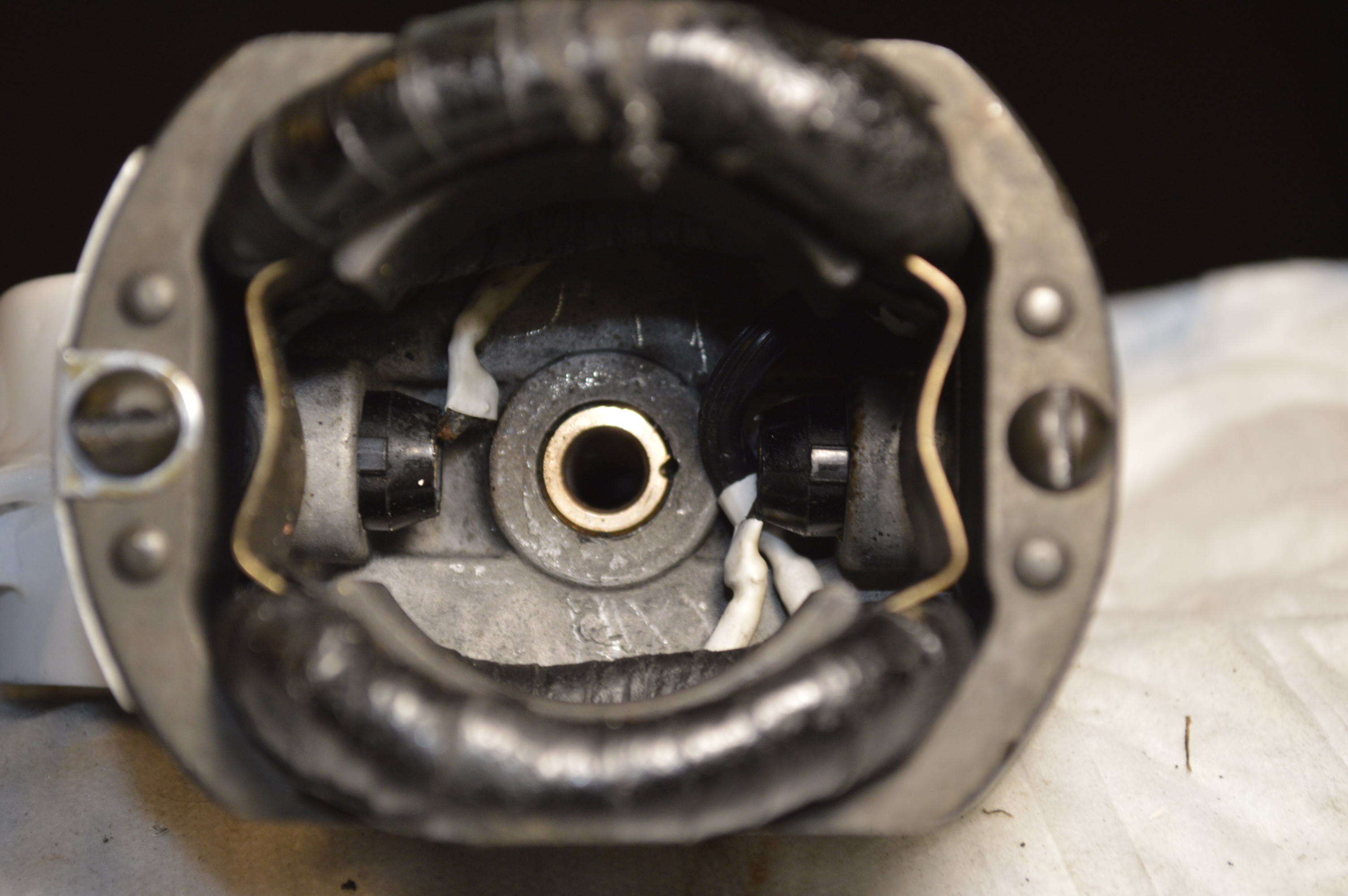
From right to left, new wires are soldered to the old wires, shrink tubing is shrunk over the solder joints, and the wires are tucked neatly into the motor case. The field coil has been installed, and looking down, you can see that there is clearance for the armature… we don’t want any rubbing parts here.
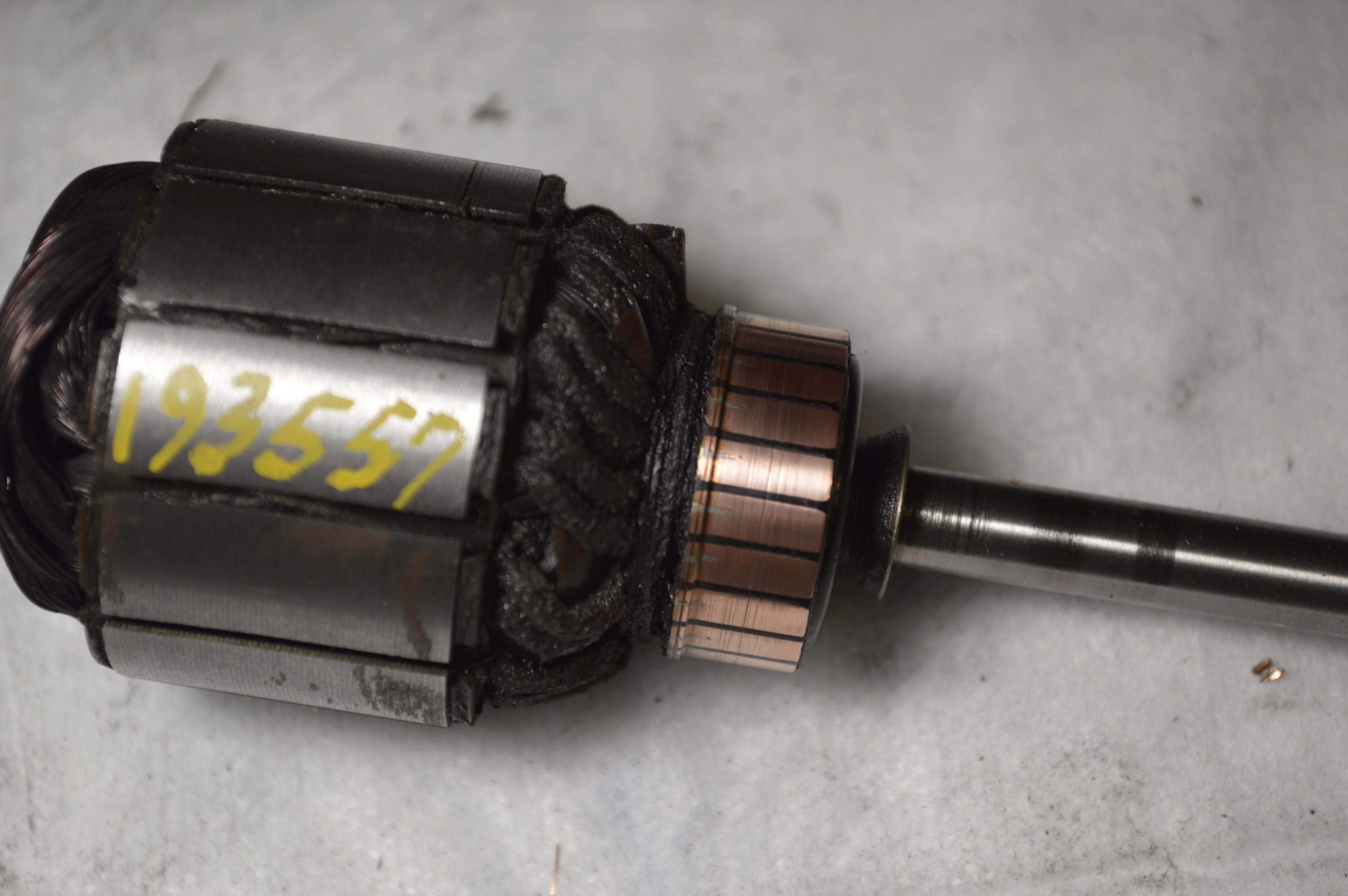
The armature commutator is polished using a dremel tool and jewelers rouge. Do not use steel wool here. If you don’t have a dremel tool, use 1500 grit sandpaper and gently clean the armature by turning the armature against the commutator. Don’t rub hard and only clean it enough to remove the crud. After it is done, it is cleaned again with the CRC.
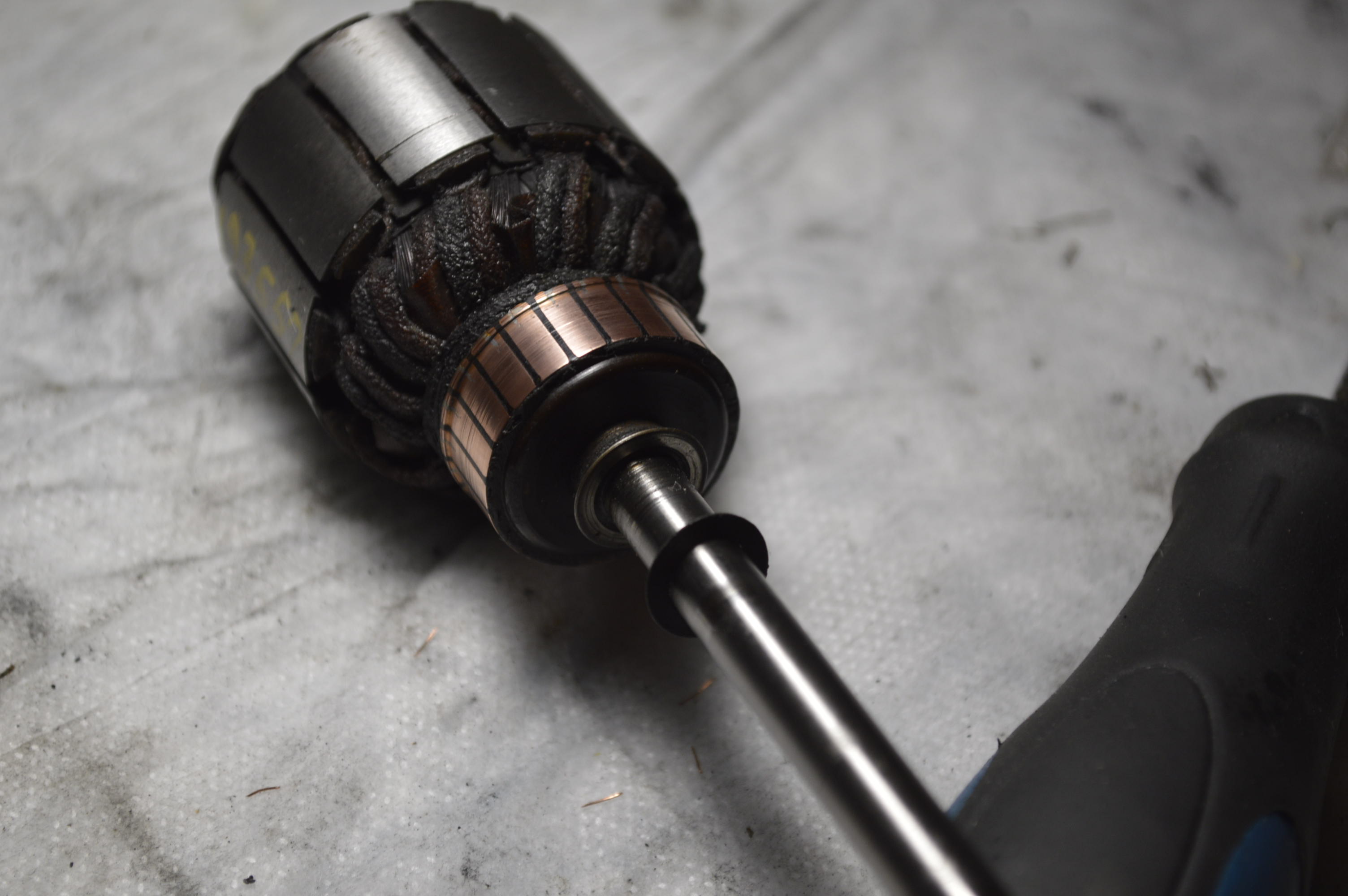
Remember that little round washer I told you to not to lose? Slide it on the shaft. Don’t put any grease on shaft just yet… we don’t want grease on the winding side of the motor. That little round washer we put on is to keep grease out. Slide the shaft into the motor housing. Once inside the motor housing, apply a little grease to the shaft, a light film is sufficient. Pull the shaft back out until the end of the shaft is flush with the bushing. slide the worm gear in place in between the bushings, line it up with the motor shaft and slide it in until it stops.
See the screw on the end of the shaft? The shaft has a flat notch in it and this set screw needs to set in that notch. The screw is removed, the shaft is turned until the notch appears, and the screw is screwed back in and tightened. The second screw on the gear is tightened next. With only the grease wicks, the motor brushes, and lubrication left to install, the job is all but done.

New grease wicks, reconditioned (The motor brushes were reconditioned by sanding the curve formed by wear flat). DO NOT USE ANY LUBRICANT unless it is for small motors. Some grease is good for gears (TriFlow grease for example) but is not intended for lubricating motors. I used Singer motor grease… Hey, its a Singer.
With the motor together, its time to start reassembling the machine. This is a pretty straightforward process and it doe not take much time. All of the gears, shafts, and rocker arm assemblies are installed.
All of the adjustments of these parts will be made before the protective wrapping is removed. The Singer adjusters manual available on line has all the information to do this to spec. Leaving the wrapping on is only a preventative measure since it will be turned back and forth to make them and I don’t want to damage any of the painted surfaces. In the meantime, I will “run the machine in” to make sure that it is smooth and all of the parts adjust to each other. Remember, Singer matched the gears at the factory and they should be installed tooth to tooth the way they were removed. I was unable to preserve any timing marks so this can’t be done now. It will be turned by hand for a while to get lubrication in the bushings, and then with a 1/2″ electric drill for 2 hours or so, adding oil occasionally. The difference in taking this step is night and day in smoothing out the machine… and it means we are getting close to the end! If there is any issue with the gear matching, I will add lapping compound and lap the gears together in their new positions… but I don’t think this will be necessary. The next step will be applying the decals. I ordered silver and gold decals… what do you think looks best!
While assembling and laying out all of the pieces, I forgot the motor cover… It needs work! In a previous picture, you can see the dent it got during shipping. With a little judicious tapping with a hammer (remember many light blows is better than 1 or 2 heavy blows will form the metal into shape and give you better control of the dent removal). So that’s what I did and then filled in the remaining dents with a light coat of bondo. After sanding, contouring, priming, and painting, it will look pretty good.

While waiting for the bondo to dry, I have moved on to reassembly of the light, and begun adjustments.
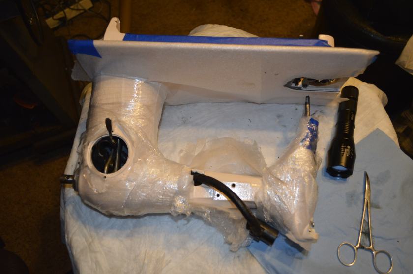
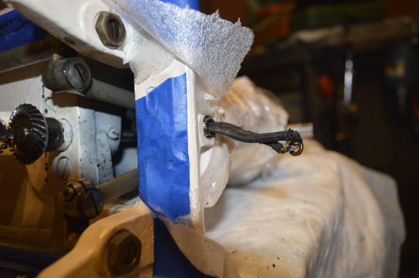

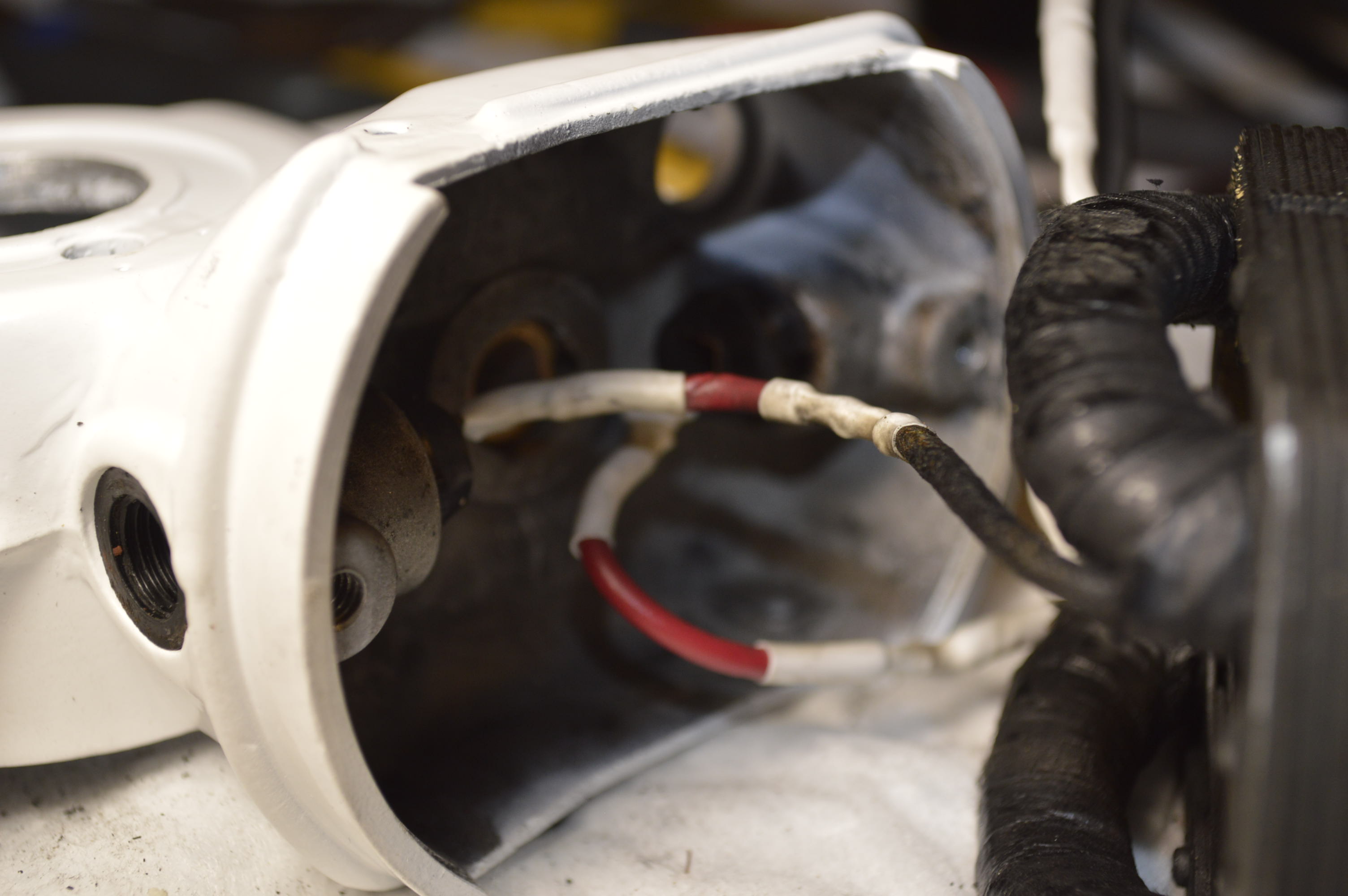
When installing the light it is very important to make sure the wire is routed properly. Hemastats or fine needle nose pliers is your friend and will help pulling the wire around and thru all of the tight places. Remember, the wire wraps around the FRONT of the vertical gear shaft, then between the stitch length arm and the rocker arm, and out thru the small hole in the bottom of the back of the machine. In other words, this wire is in close proximity to parts that are moving very fast when the machine is running, and contact with any moving part and this wire will end badly. I have tried to show the routing of the wire in the pictures.
Starting to put all of the parts on and it is starting to resemble a snake shedding its skin… well, more like a Singer 201.
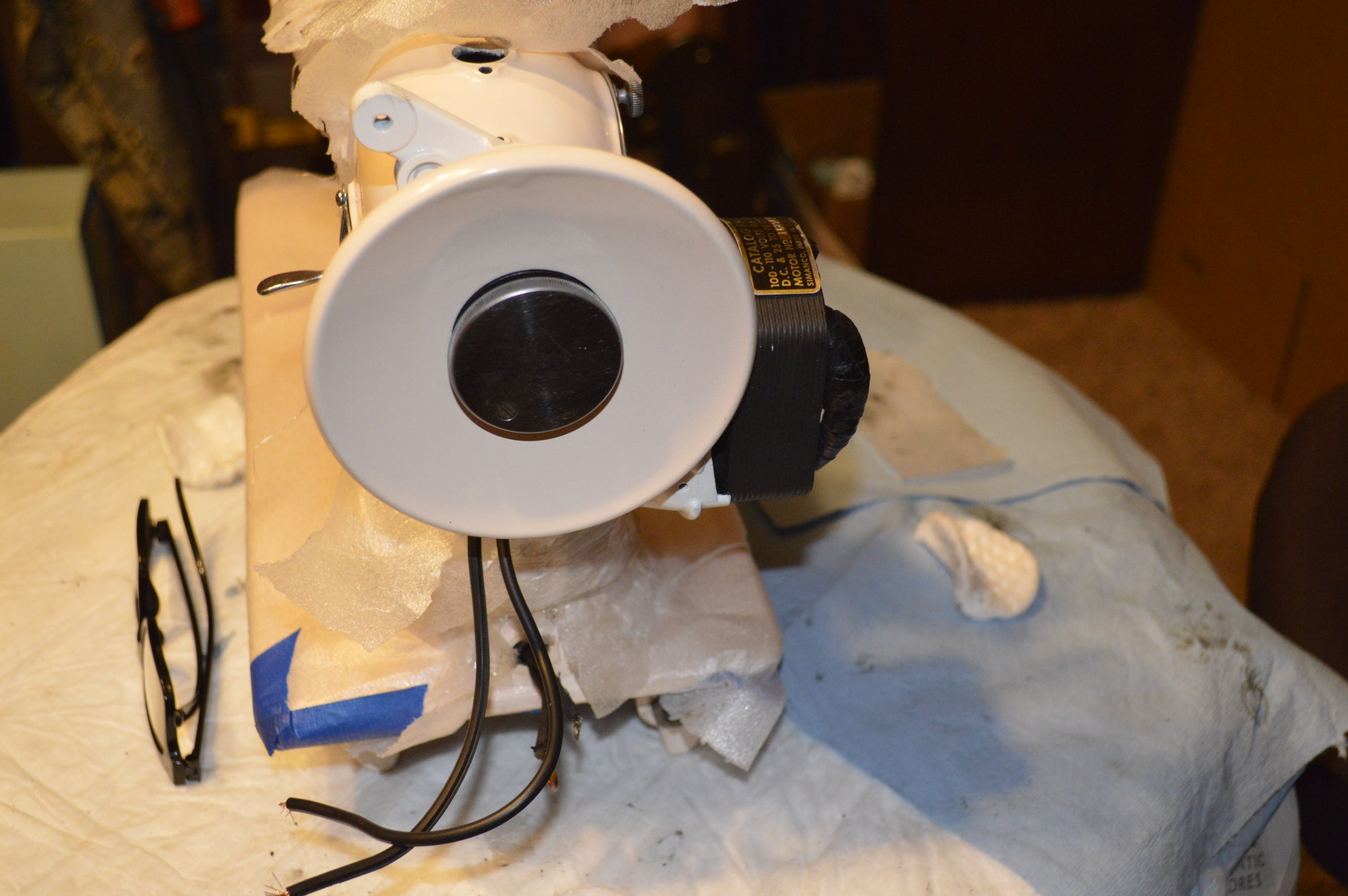


Soon, the wrapping will be removed and the machine prepped for decals.
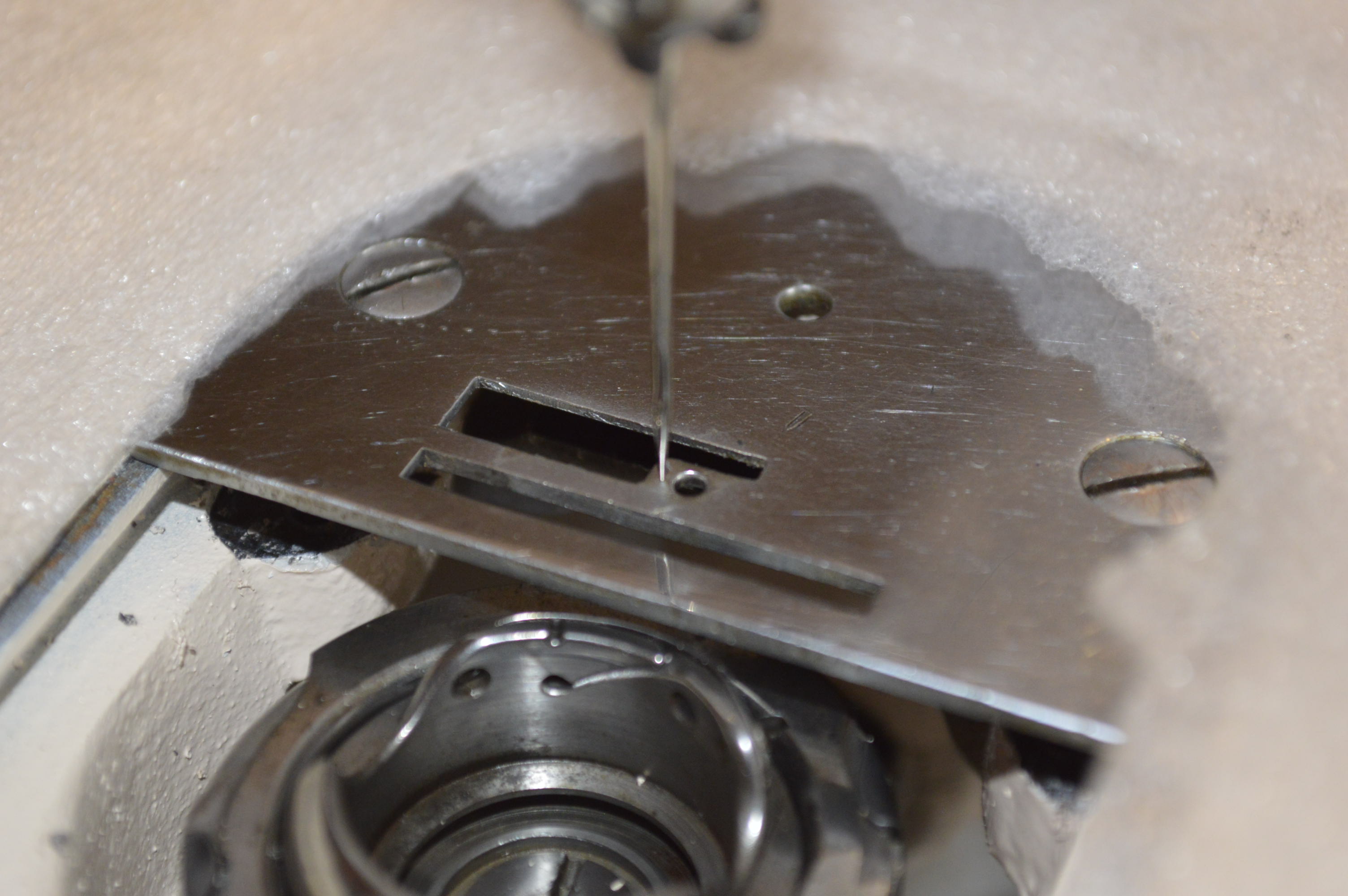
DISASTER! I don’t know how these things happen… I really don’t. I did not realize I had a BIG problem until I started assembling the bobbin hook thread clearance guide when I noticed the needle hit it… and not by a little either. So I checked the head assembly and needle bar. No problem there. I put the needle plate on and this is what I found.
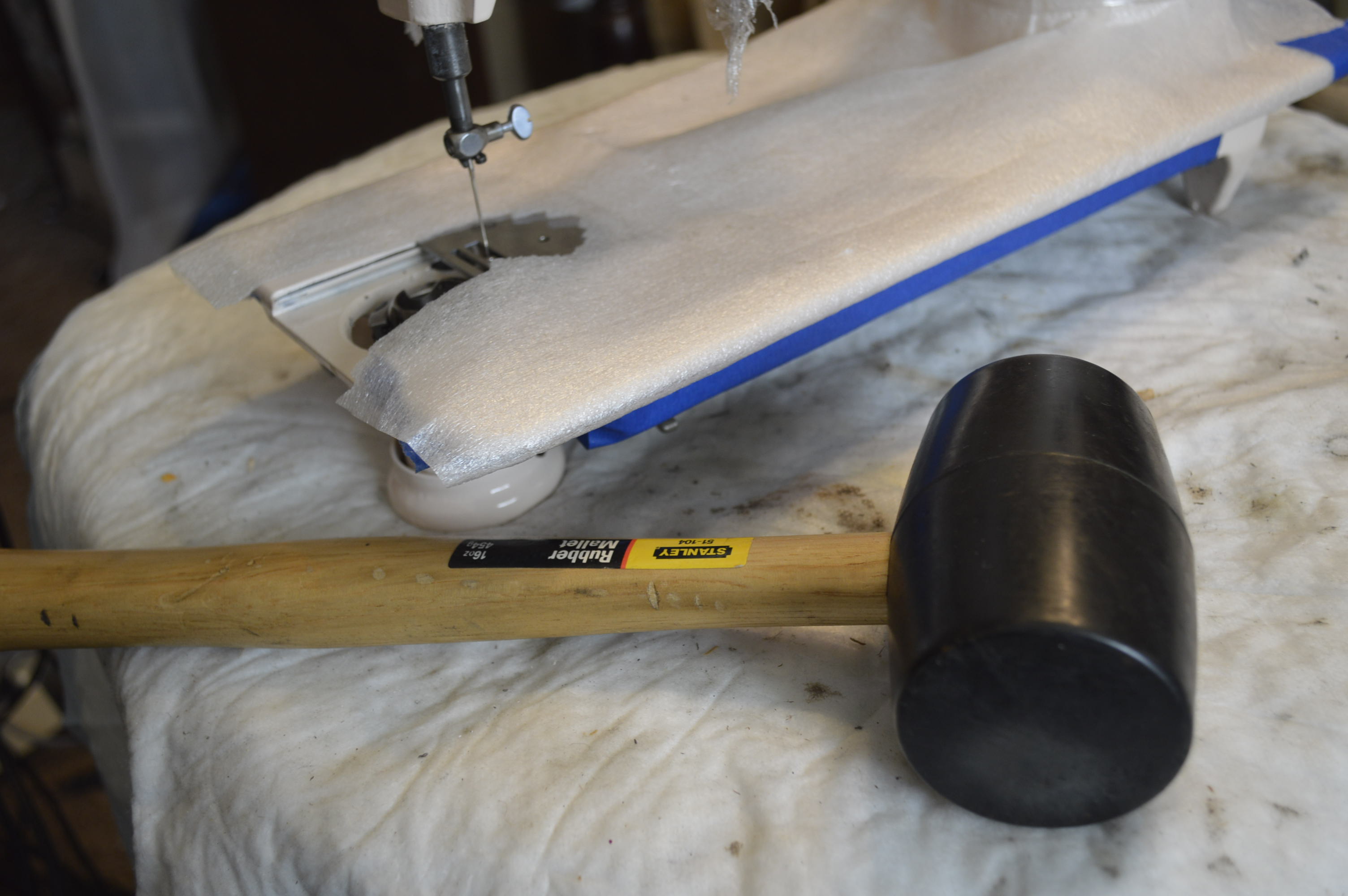
At this point it is obviously a misalignment with the sewing machine bed and the head. Now, as I said, I don’t know how this happened. Is it because of the crack I repaired? I don’t know but the crack was tight and I don’t think so. The bottom line is that the project stops here, or we get medieval on it. Well, its too late to stop here. So here’s what we do… we separate the head from the bed and realign it. Now, unless you are prepared to do some serious work, no need to read further. If you want to see how it’s done, and think “why not? It’s not MY machine” then read on. now to do this, you will need a big rubber mallet and and a impact driver.
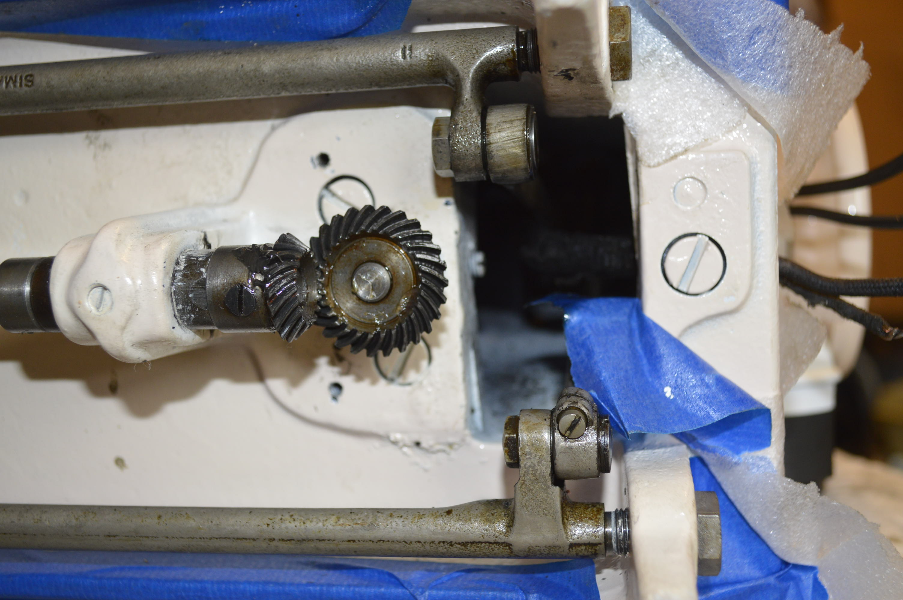
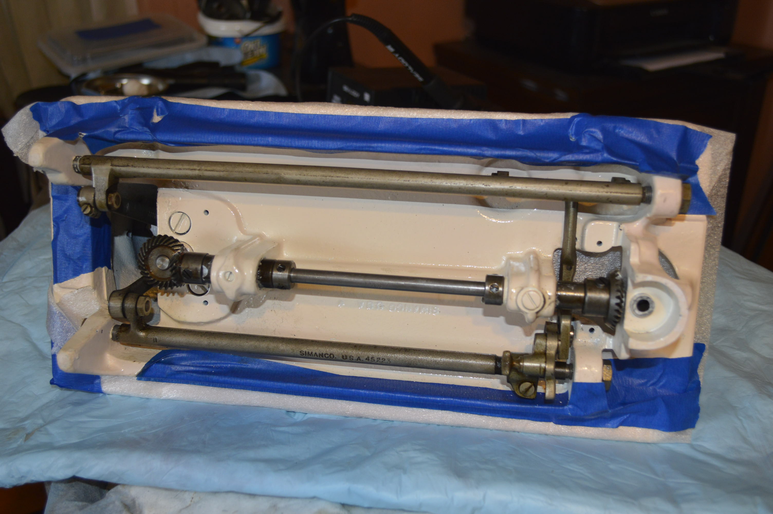
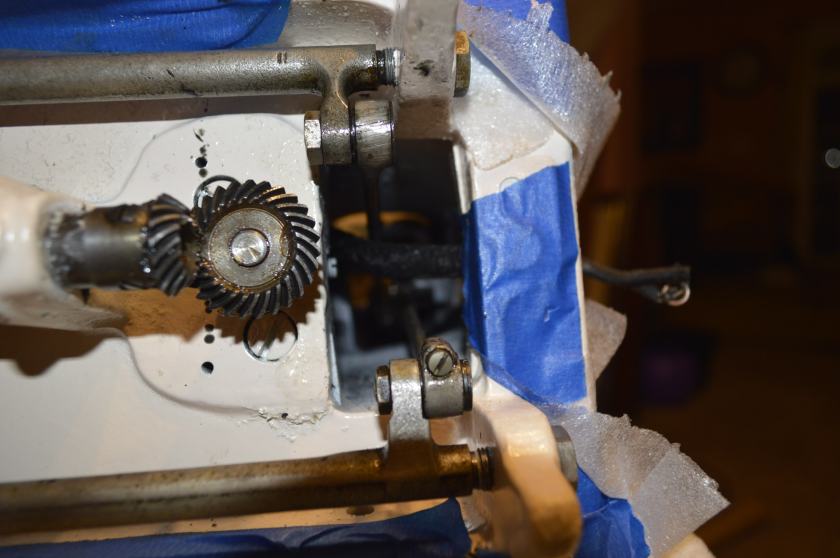
See the three big bolts? These need to be removed with a impact driver. This is where you need an impact hammer… they will not come loose with a screw driver. See the smaller set screw just to the right of the gear? This tightens the gear shaft bushing. All of the gears and rocker shafts , and balance wheel have to be removed.
After removing these components, all you have to do is hit the side of the machine bed until it starts to loosen up. Nothing more satisfying than beating the hell out the beautiful prepped paint work that to so long to achieve… and it took a lot of beating.
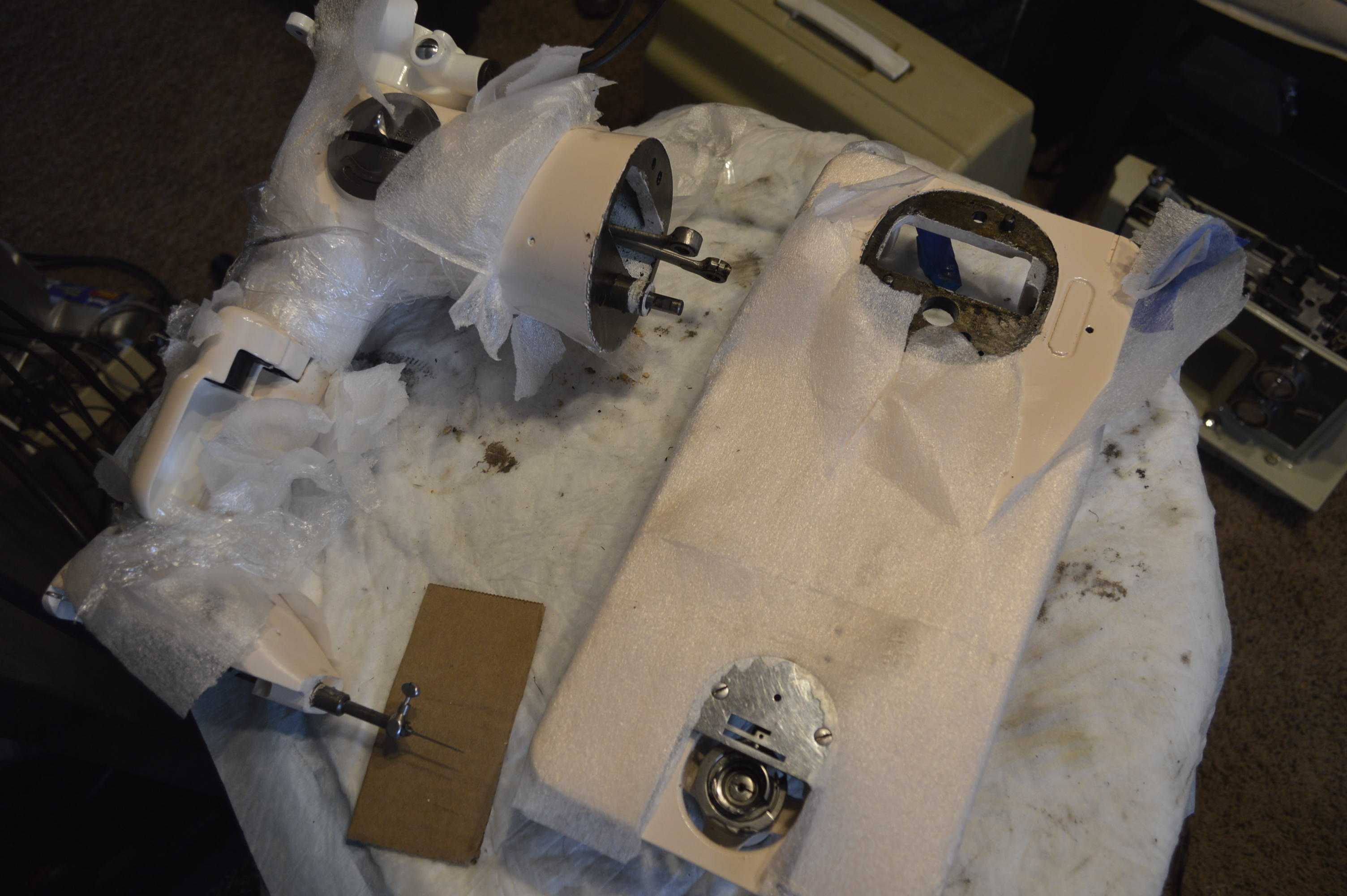
If you look closely, you will see 2 dowel pins in the bed that align the head to the bed. These are hammered out and the head and the bed are reattached with the 3 bolts. The trick is to leave them loose enough to align the head and snug them down without loosing the alignment. Easier said than done because the machine has to be on its side and the head is acting like a 30 pound wrench.
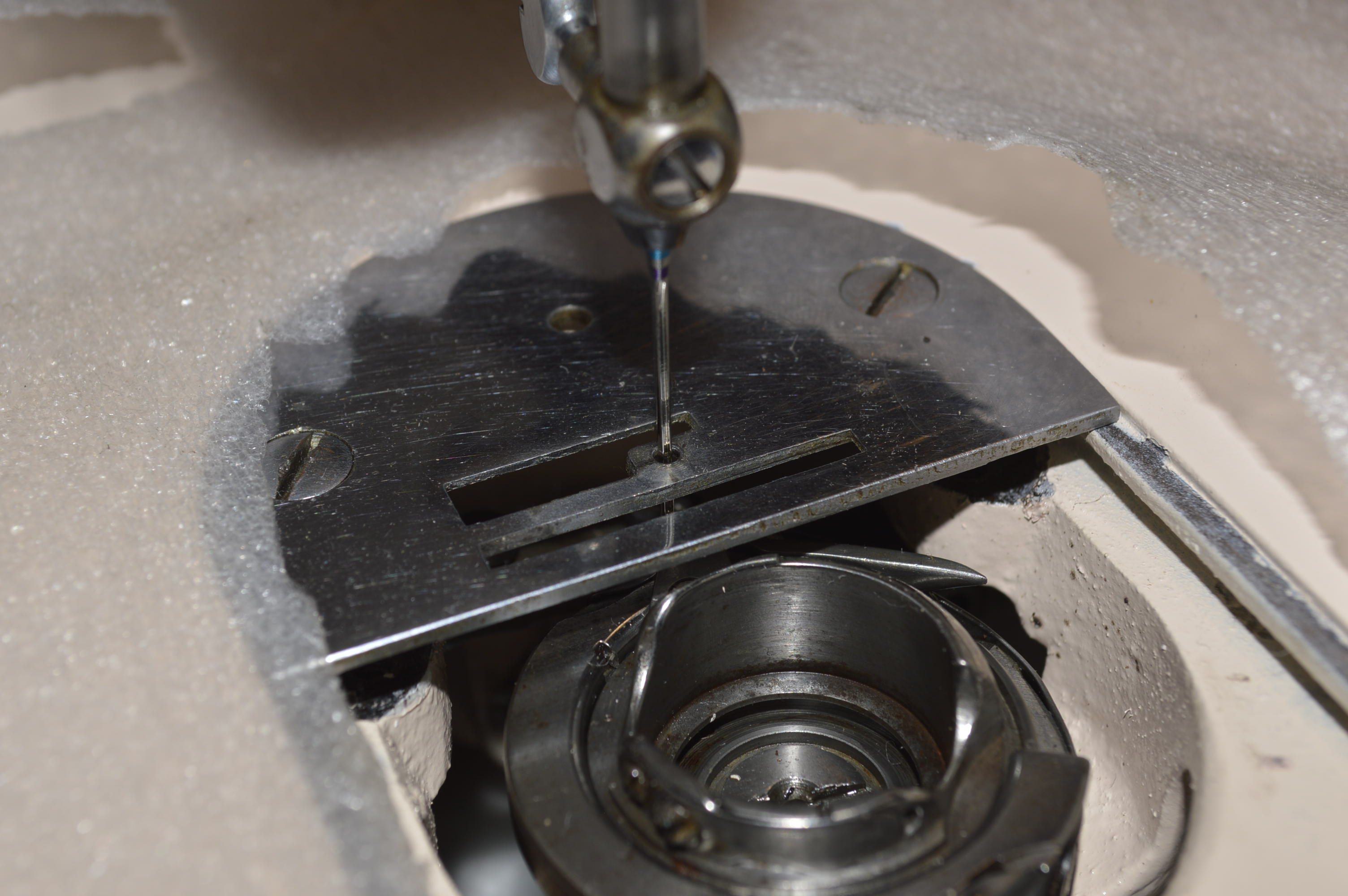
So it looks like the needle is centered in the hole… that’s good. But there are two axis of alignment here, hook timing and hook to needle alignment. We got the side to side, but what about the front to back?
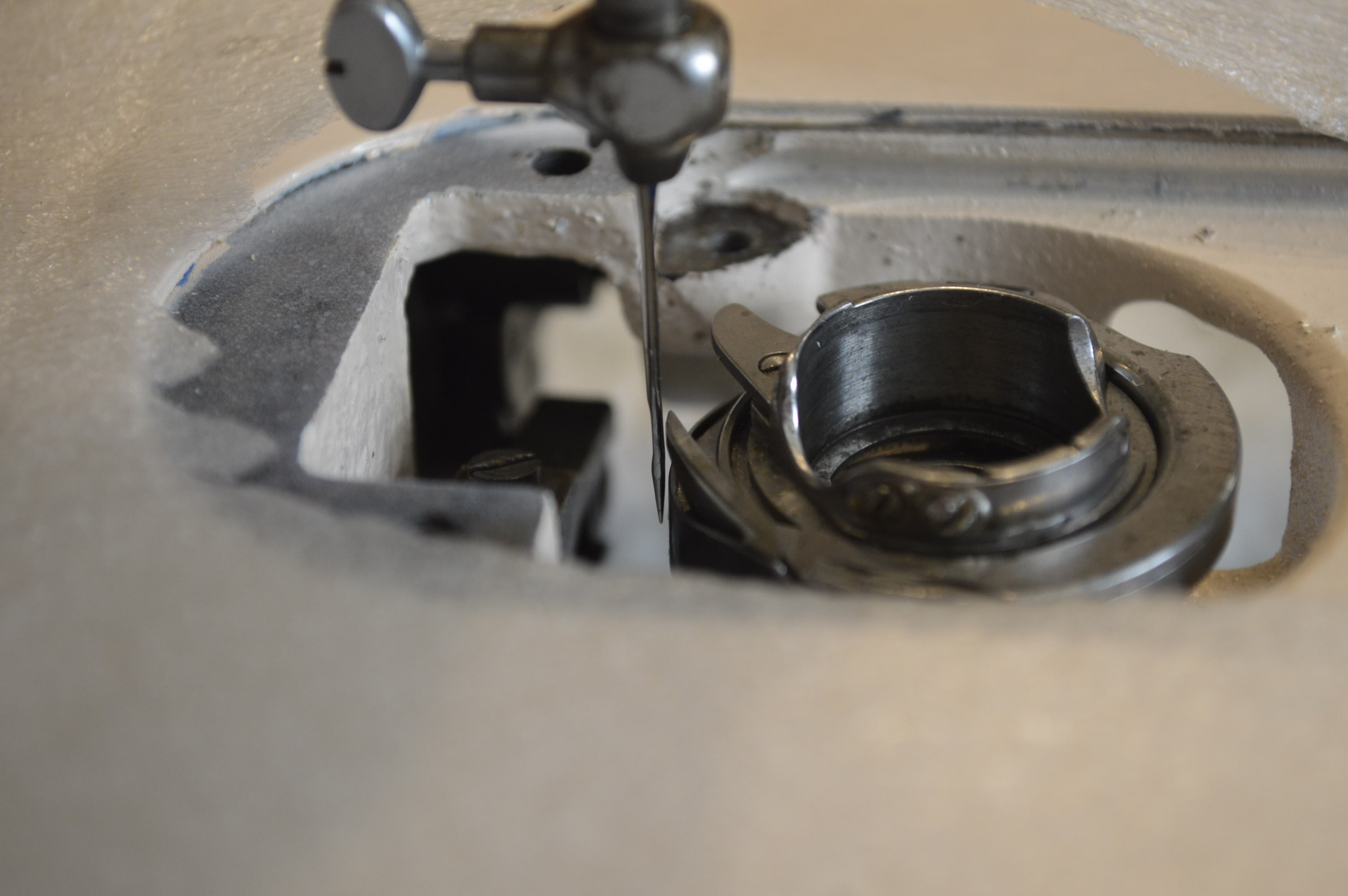
Notice the gap between the needle and the hook. This is a very tight and critical alignment. I need to reference the service manual to see if this is close enough… if it isn’t, we’ll need to readjust the alignment. But I don’t have it in me to beat this machine any more today. Just thinking about all of the work it will take to repair the paint damage is enough for one day. One cardinal rule to remember when working on a sewing machine, is to never let the sewing machine know you are in a hurry!
March 28
Gee, it’s taken so long to this to this point that I figured I better make it a timeline. It turned out that the gap was too wide. Tolerance was 0.000 to 0.003. I didn’t show the process but I did disassemble and adjust to 0.000 clearance. I didn’t need the hammer this time. Now, I for some reason you decide to split one of these thins in half, know from the beginning that it changes a LOT of tolerances. I had to adjust the depth of the rear spiral gear shaft and adjust the drive system all the way to the bobbin case. Now I am going to try to get it to sew before I resume the cosmetic repair/restoration.
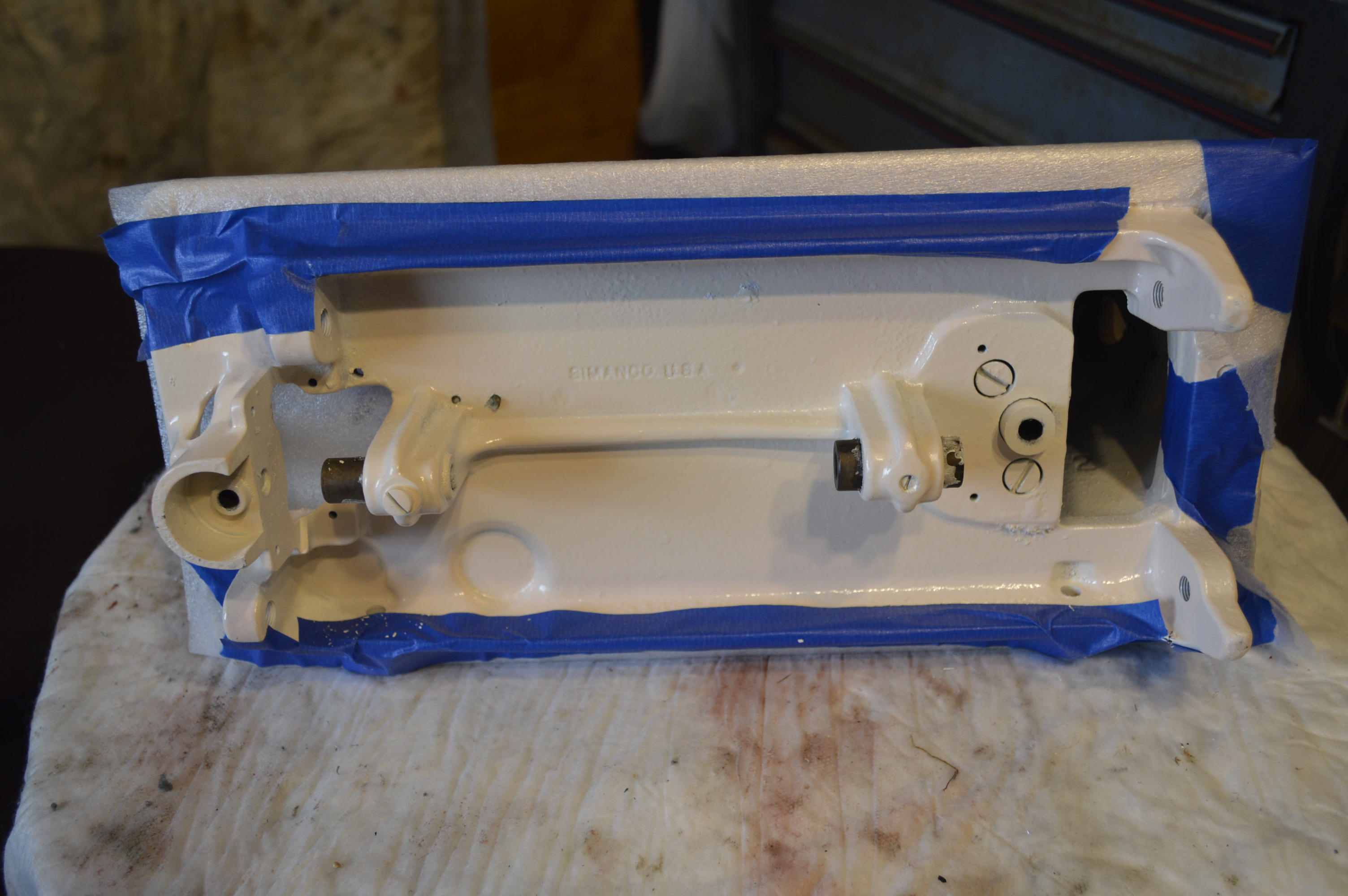
No surprise that the crack came back… as well as the paint seam at the pillar and the bed turning into a ragged mess. While the machine was in 2 parts I sanded the paint at the pillar and the bed to make it easier to repaint it… This is what it looks like now!
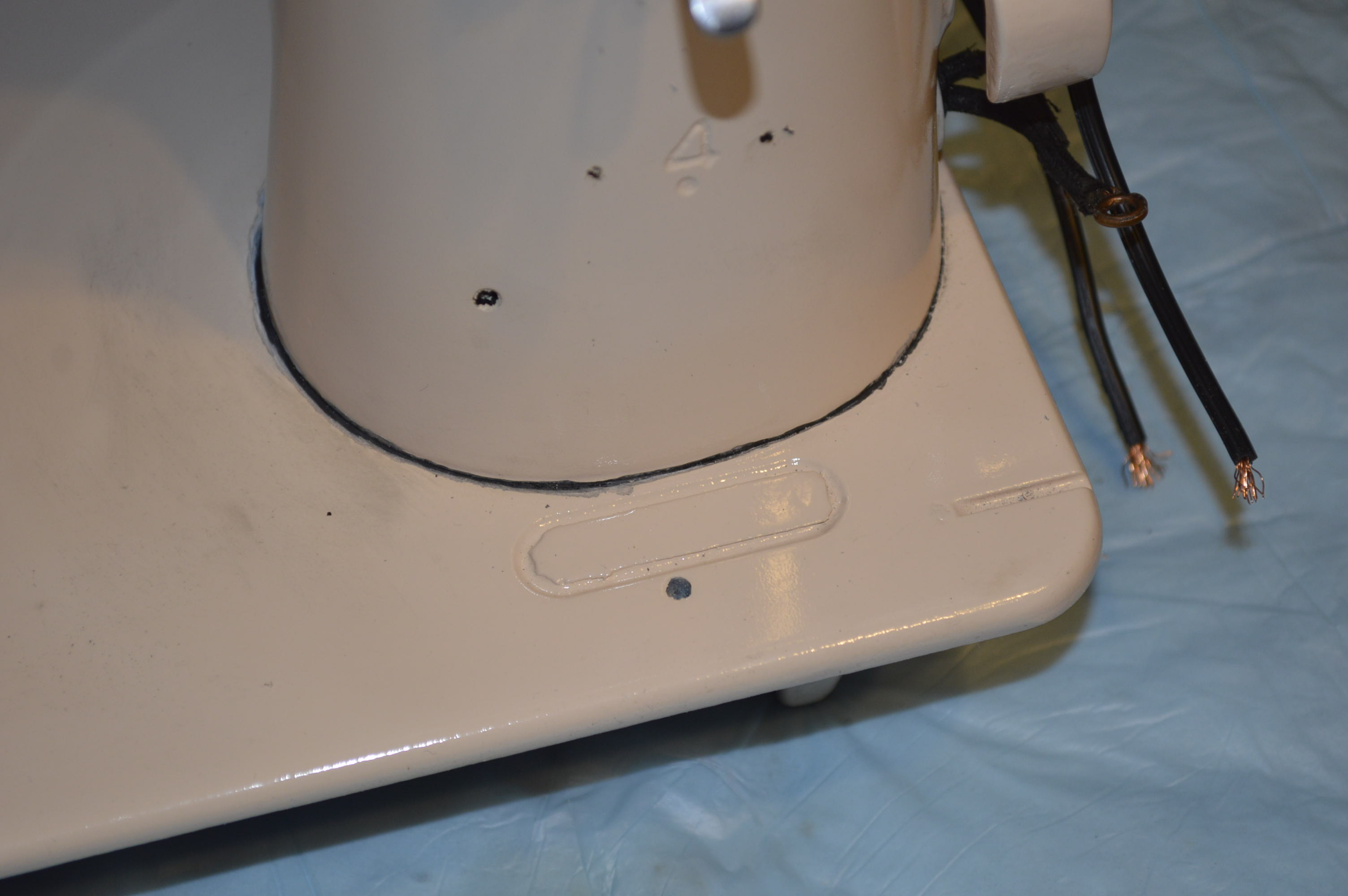
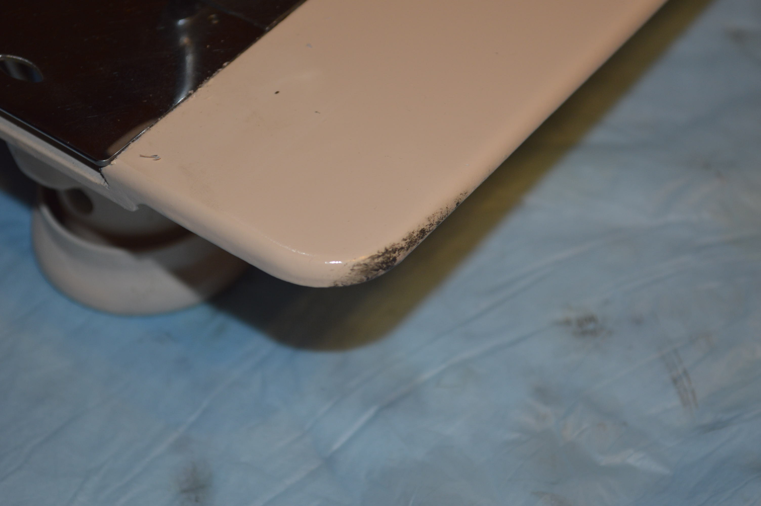
It really looks worse than it is, but it is going to be a lot of work to make it look like it did. Oh, I have a surprise!
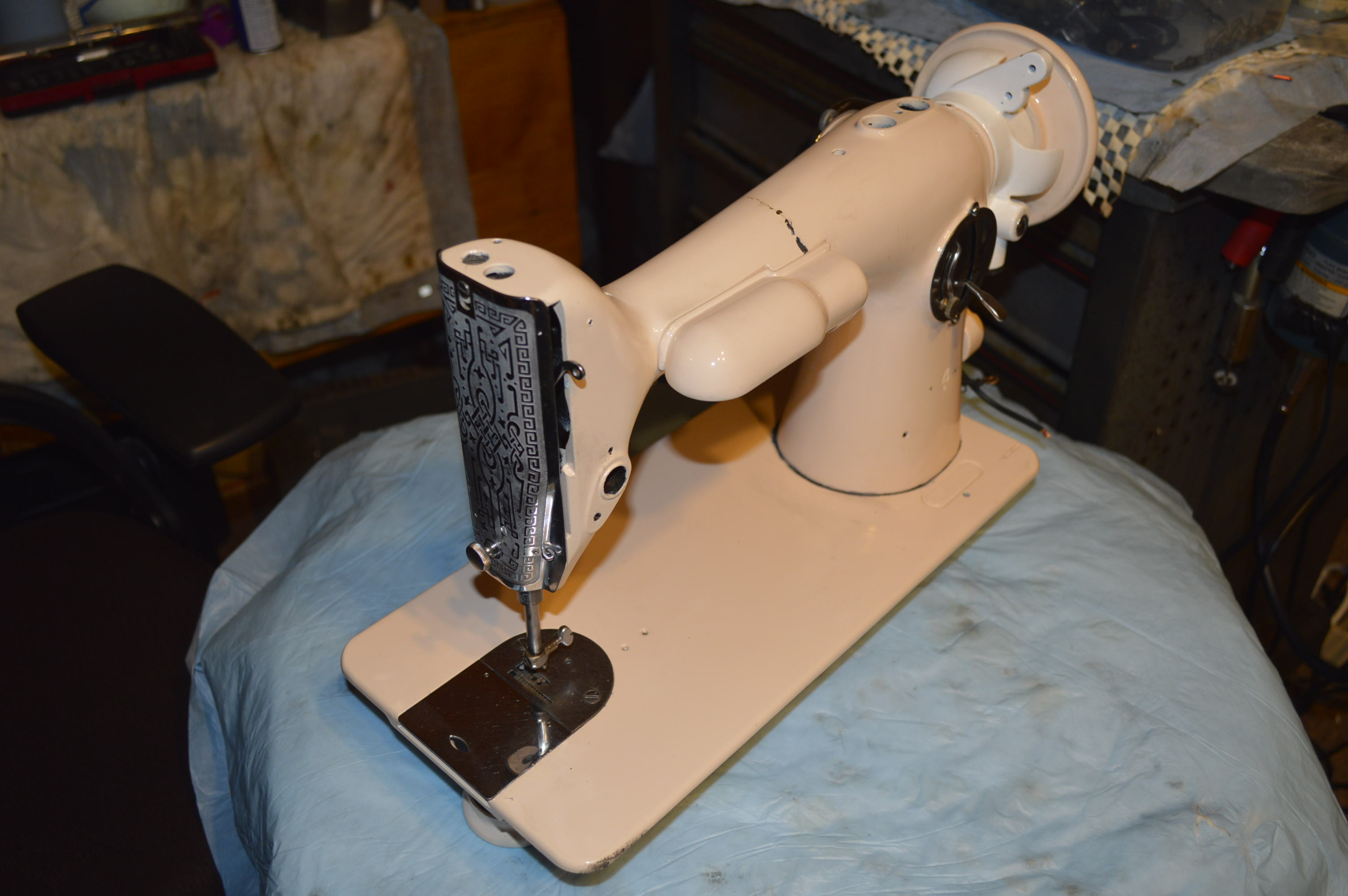
I put the face plate on! Isn’t she looking pretty! Actually, I did this for me. I needed something to remind me of her potential. Forget that there is no needle bar or tension assembly. Those are little things, and my advice for today is don’t fret over the little things!
April 14, 2019
It’s been awhile since I have had the opportunity to revisit this restoration. Aside from being busy keeping up with other projects and priorities, I finally had a chance to make progress. Now, to be quire honest, I didn’t know how this was going to end… There are many adjustments that were necessary that were never contemplated when the machine was manufactured. The alignment of the sewing arm to the bed is set by dowel pins… they are gone, and the arm was “twisted” and “adjusted” with the aid of a hammer. The gear bushings had to be adjusted to accommodate these changes and the gear lash fit by feel. Remember, these gears are mated at the factory and the tooth to tooth orientation was lapped for smooth running. There is no way of knowing what else is going to pop up and make me groan. I decided to make sure she sewed before spending the hours it will take to cure the cosmetics, even before applying decals…
So… I put all of the parts, bits, and pieces on the machine, popped in a class 66 bobbin, put a needle in the needle bar, completed the wiring, and proceeded to check her out! The first turn of the balance wheel and the needle picked up the bobbin thread… good sign. I put a piece of cloth under the presser foot and turned the wheel again and it made a stitch. A few more turns produced a few more stitches!… I attached the foot controller, pushed the pedal, and she began to sew! The stitches were well formed, the tension was balanced (luck), and the fabric feed was straight! I passed it on to my Wife, and she proceeded to run the cloth thru at full speed. Must have made 10,000 stitches before she stopped to let the motor cool.
This was done without a single adjustment made except by eye and feel. I am certain that once the proper adjustments are made, she will sew beautifully for another lifetime. This 201-2 is a true heirloom machine, never meant to sell. Again, I am impressed with how tough and durable these old cast iron Singer machines are. I am encouraged and ready to continue the full restoration to completion!
Well, that’s all I have for now. If you are interested in following my progress to completion, check back frequently… Thanks!

You really make it seem so easy with your presentation but I find this matter to
be really something that I think I would never understand.
It seems too complicated and extremely broad
for me. I’m looking forward for your next post, I will try to get
the hang of it!
LikeLike