
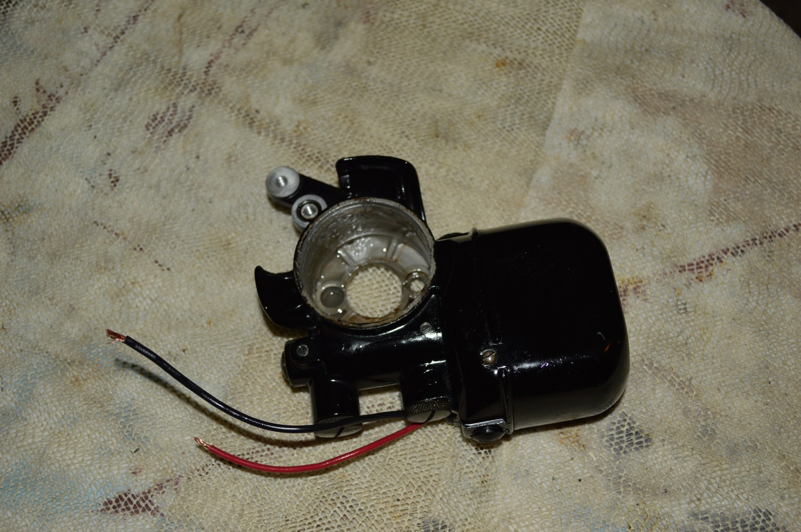
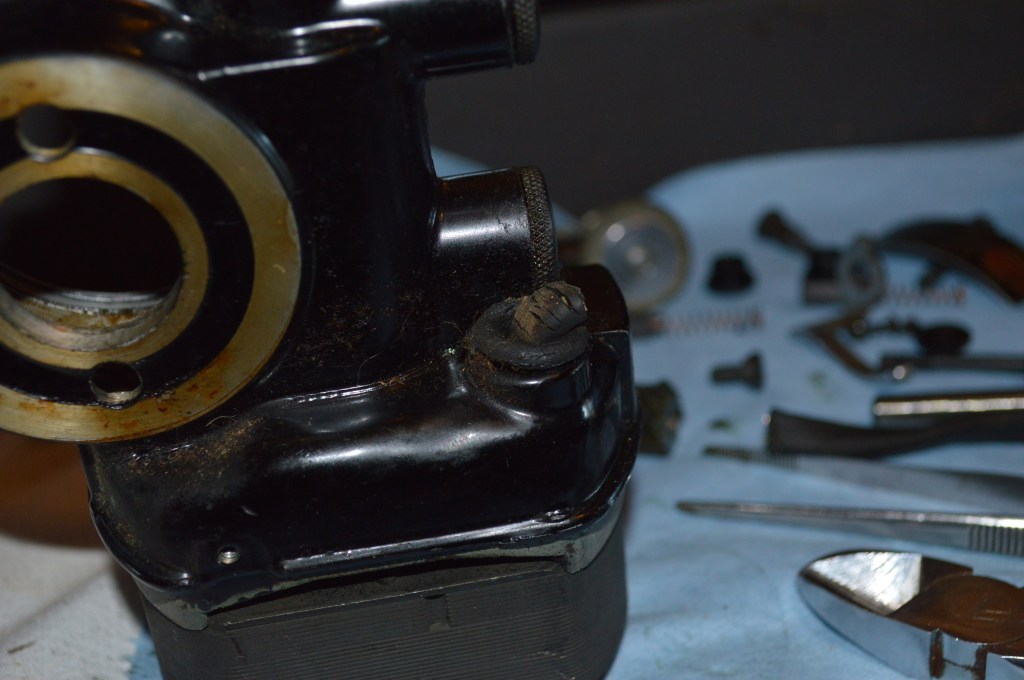
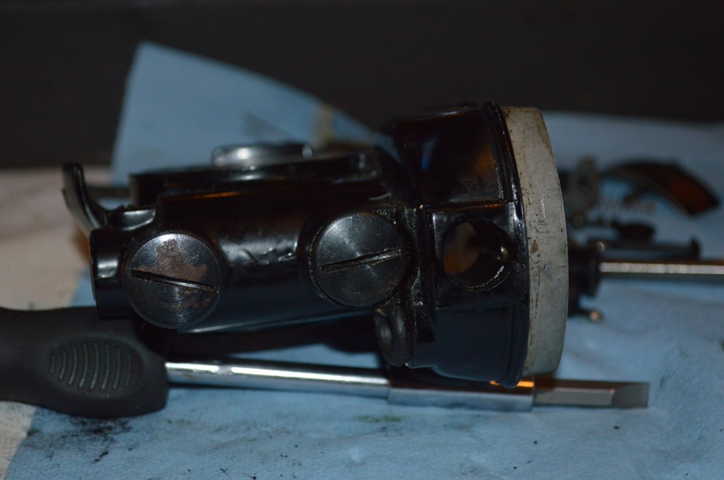
First a picture for those wondering what a Singer “potted” motor is…
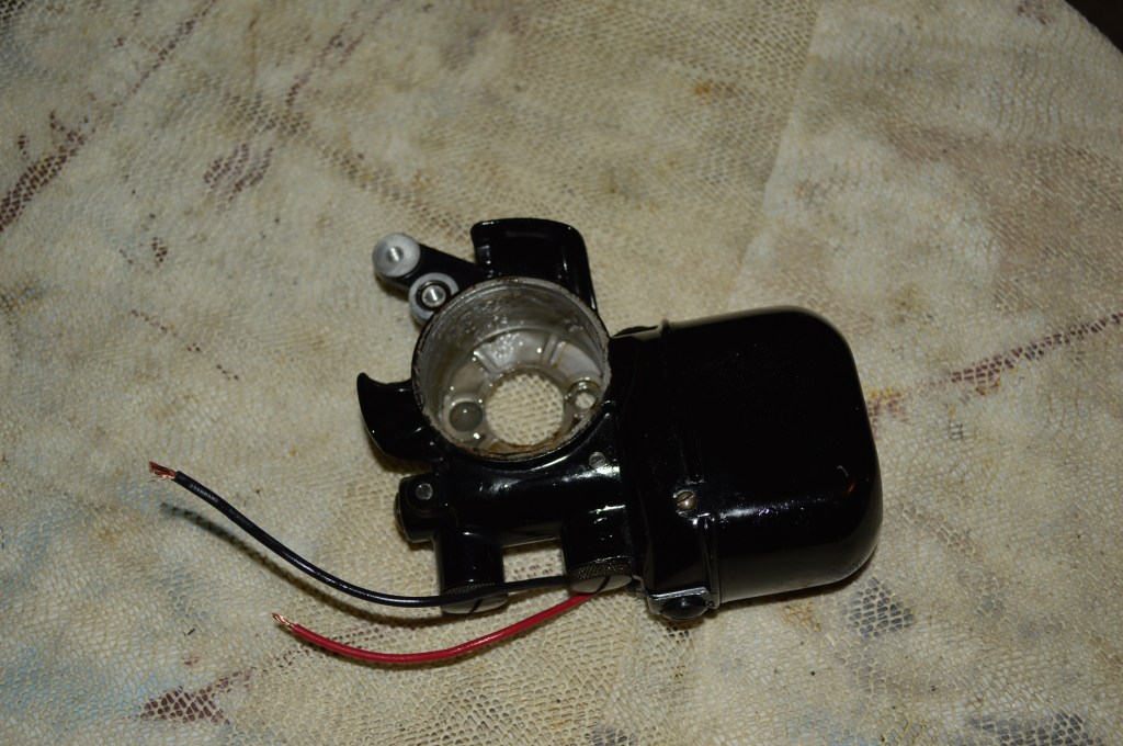
A potted motor a direct gear drive motor where the motor housing is attached to the back of a so equipped Singer sewing machine. The motor drives the sewing mechanism via a gear on the balance wheel. The motor case protrudes from the back of the machine and kinda looks like a pot… a potted motor.
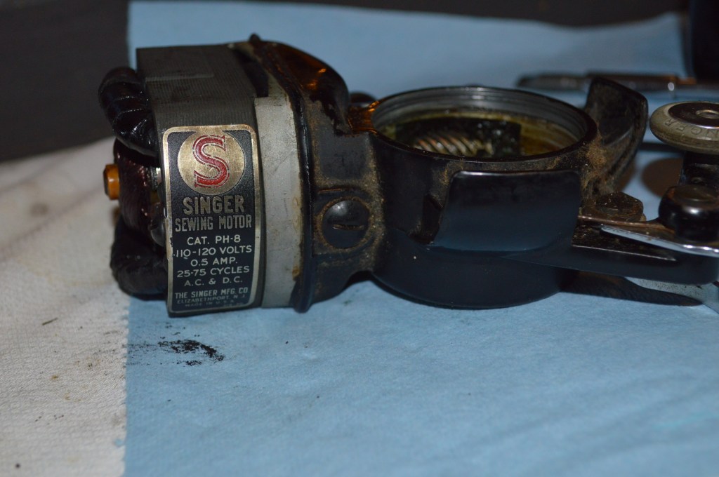
Singer only offered the potted motor on a few of its machines, these include the Model 101 (different design), model 15-91, and the model 201-2. Some have described the Singer potted motor as the best sewing machine motor ever made for a sewing machine. I don’t know about that, but I do agree it is a fine motor. They are still found on many machines running today that were manufactured when it was first introduced in the 1920’s . Imagine a sewing machine motor made today that will last 100 years.
In my opinion, it has some drawbacks. First of all, if it does go bad, it must be replaced with another aged vintage motor. They are not manufactured today…. even in China. The machine will not work with any other style motor. An external motor on the other hand can be replaced easily. This is a serious consideration for someone considering a Singer model 15-91 (potted motor) or a Singer model 15-90 (external motor and belt). The machine doesn’t care what runs the sewing mechanism… I would bet that there is someone, somewhere, who adapted their belt driven sewing machine to power it with a chainsaw motor… I’ve thought about it myself. Anyway, that’s off topic. This tutorial is about restoring the potted motor on your machine so you don’t need to replace it.
As I said, it is a great motor and it was designed to be serviced and repaired. The achilles heel for these motors, and most likely why you have read this far, is the wires. They all suffer the same fate. The motor was designed to last for decades, but unfortunately, the wires don’t.
So, getting on with this tutorial, I must tell you up front that it is a long and extensive blog because I am going to show you how to restore this motor to the highest degree possible… There are instances where a motor will burn thru a winding (The thin copper wires wound in the motor), in which case, there is no hope left and a replacement is the only cure. I can’t wind a motor, you can’t wind a motor, and if you did find someone who could wind this motor, the cost would not justify the service. Still, there is much that can be done to turn the clock back decades to restore this motor to its youthful vigor, and this is what I want to share with you in this tutorial.
The steps will be shown in order of process. To try and keep this post to a reasonable length, I will not use much space for discussion, but will caption the pictures to describe the steps. If I think I need to explain something outside of captions for clarity, I will stop and do so. You can do as much or as little as you want. No matter how deep you go, the reassembly from a certain point is simply the reverse steps up to that point.
Note, the pictures in this tutorial show several different potted motors, It ain’t a “bait and switch”, but because I document all of my restorations and I have plenty of pictures combined to show each step in detail. The grease that I refer to for the grease wicks is petroleum jelly. Don’t frown just yet, the reason is revealed in the tutorial. The grease for the worm gear is Tri-Flow synthetic grease, Singer sewing machine grease will work well too… but use these only on the gear, not for the grease wicks… yep, two different grease types for two different applications. That said, lets begin:
Disassembly:
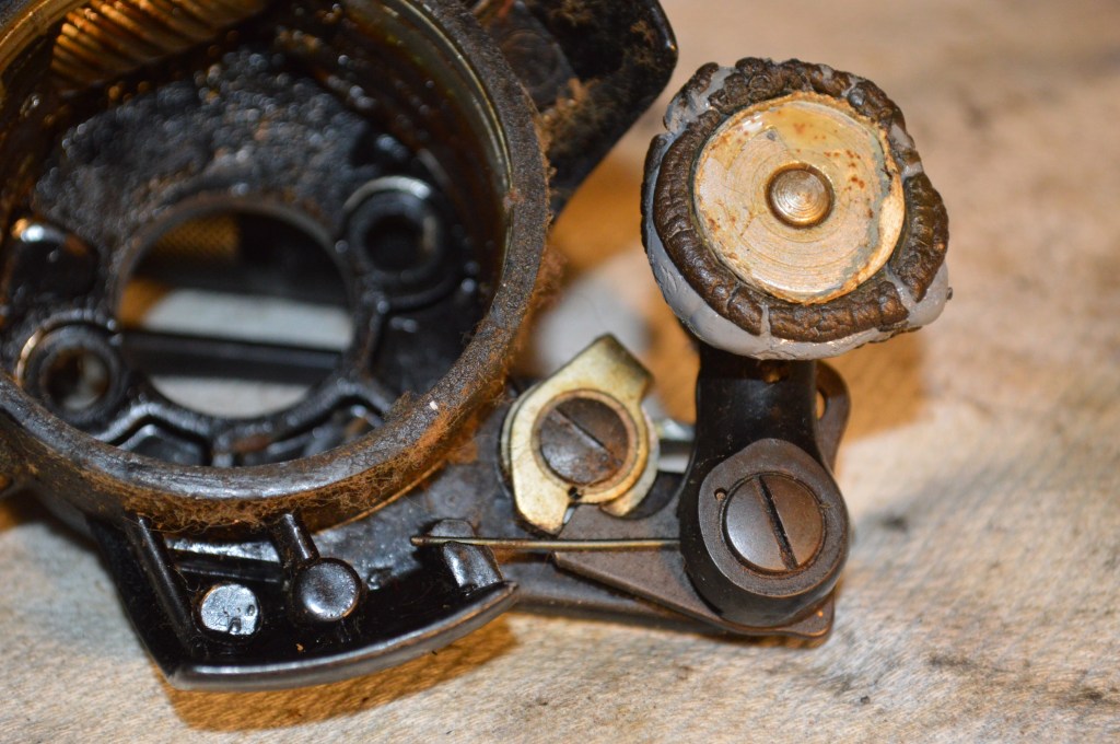
Remove the balance wheel by loosening the stop screw in the stop motion knob on the back of the balance wheel. Set aside the balance wheel, the stop motion knob and the washer for reassembly. Removing the bobbin winder aides in cleaning. This means removal is optional. It has springs that for some folks can be difficult to reassemble. Don’t disassemble if you are unsure… better safe than sorry.
Remove the bobbin winder assembly 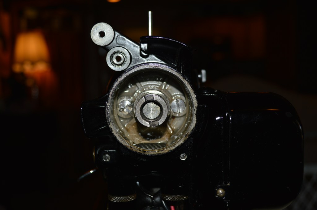
Note these 2 screw bolts that attach the motor to the machine
These 2 screws are tight. They must be removed with a tight fitting screwdriver. The easiest way to remove these is to press the screwdriver hard into the screw slot while lightly tapping on the end of the screwdriver with a hammer as you are trying to loosen it. This impact will loosen them, simply trying to loosen them with all your might will not. This is most important… You will NOT get them off simply trying to loosen them. What you will do is strip out the slots trying. Use a little impact, it works. Lay the motor on your bench.
Sometimes it is easier to remove the bobbin winder assembly when the motor is removed. Be warned, these screws are pretty tight too. 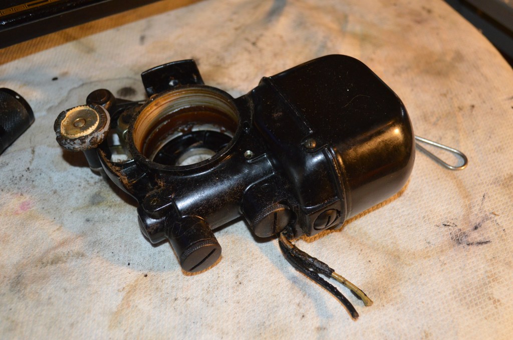
The motor cover has 2 small screw that hold it on, remove these and remove the motor cover.
Removing the cover will reveal the armature. To remove the armature, follow the next steps. 
Notice the small screw cap between the gear and the end of the motor. There is one on each side of the motor. These are the motor brush caps. There is a spring behind this cap. Remove the cap without loosing the spring. Be careful, the springs can fly out and these caps are bakelite plastic and can break. 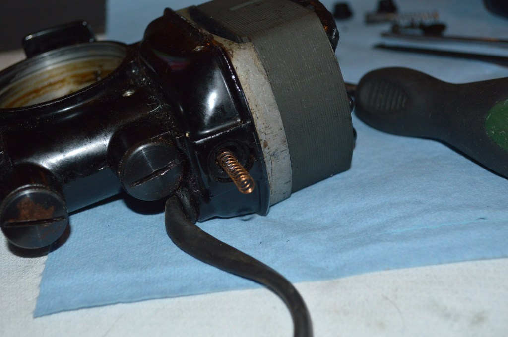
Brush spring exposed, Pull the end of the spring and the brush should slide out with the spring 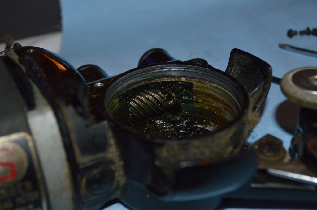
The armature is held in the motor by the spiral gear. There are two screws that hold the gear to the shaft. Loosen these and pull the armature straight out of the motor housing. Note… one of these screws tightens on a “flat” milled into the shaft. This is important in reassembly 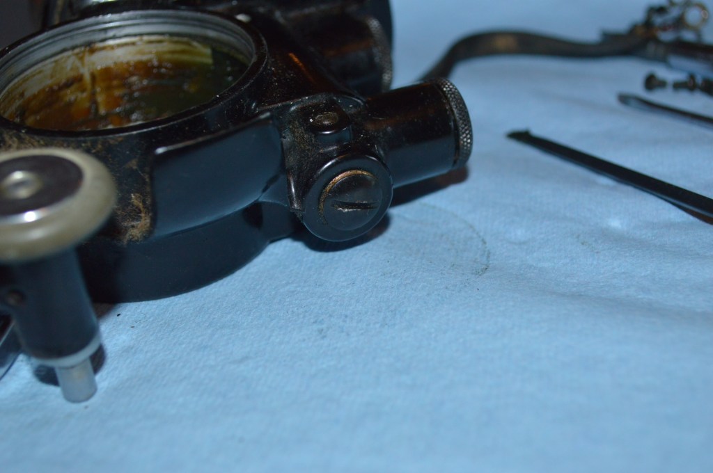
Remove the armature shaft end cap 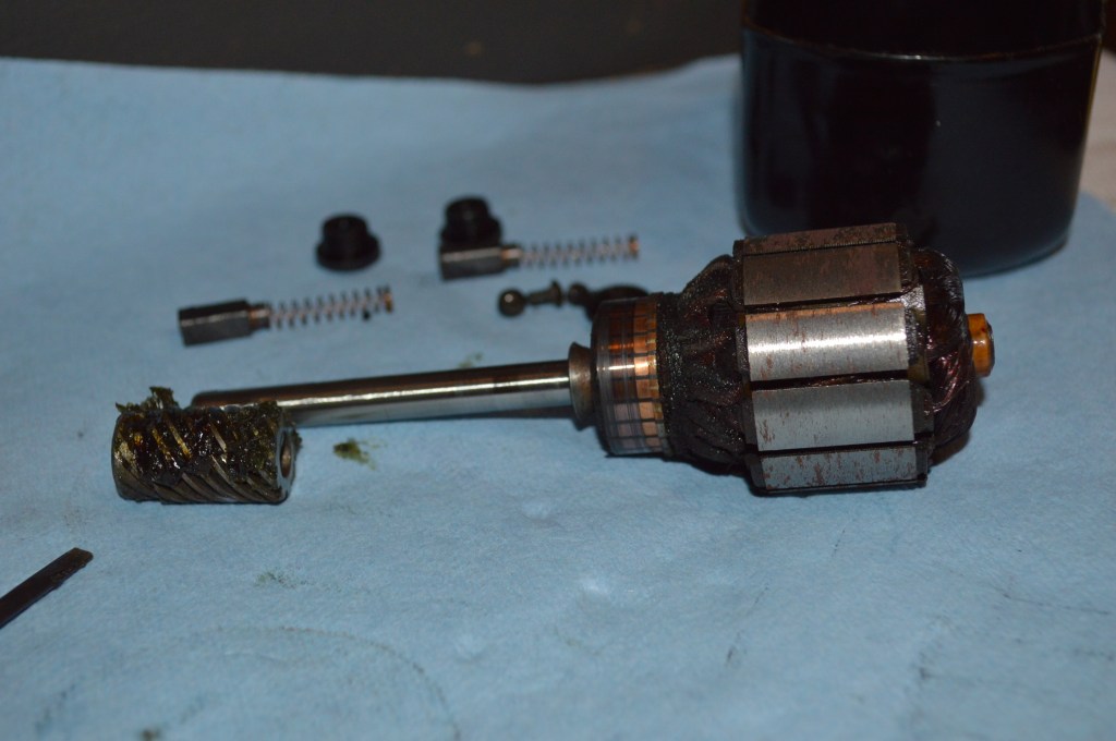
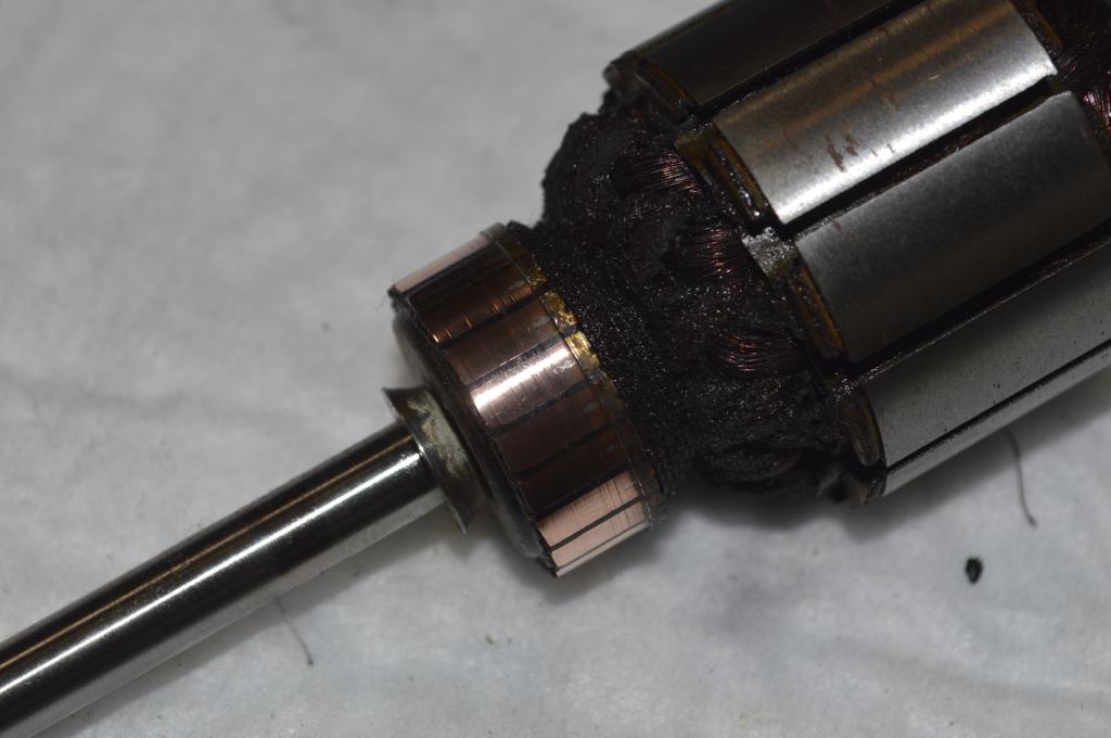
Here are the brushes, armature, and spiral gear removed.
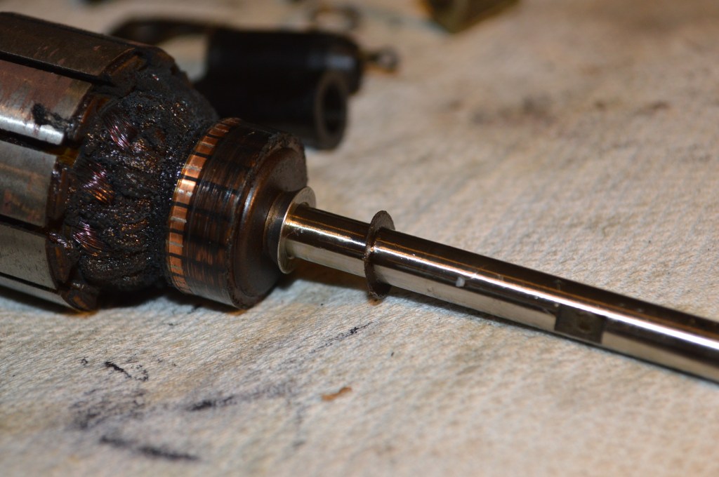
Important! There is a thin washer on the armature shaft. You may not notice it immediately, but it is there. Be careful that this washer in not damaged or lost. It prevents the motor grease from migrating into the motor housing. You can see it here.
Moving on, the next steps require soldering and desoldering. To be successful, you need a hot soldering iron. I use a digital soldering station at a temperature of 450 degrees centigrade, or a hand held 250W soldering gun. A small hobby or wood burning soldering iron may not get hot enough to handle this size wire. The most important consideration in any de-soldering/soldering operation is that you need enough heat to melt the solder quickly. To much time melting the solder will heat the wire and possibly damage the insulation. Note: This step is not necessary but for my needs it is part of a potted motor restoration. Likewise, the motor housing can be cleaned without removing the brush tubes.
Cut the wires entering the motor housing 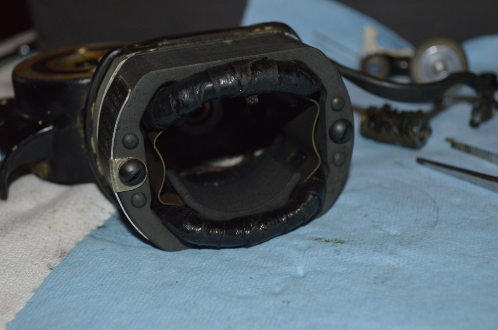
Remove these 2 bolts to remove the field coil 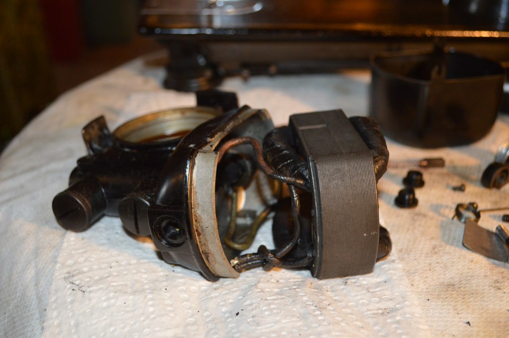
Carefully pry the field coil away from the housing 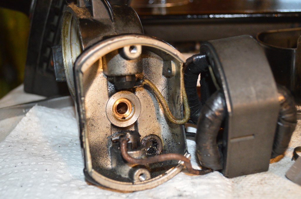
Gently open up enough room to access the motor brush tubes to de-solder the wires. When the solder melts, you can wiggle the wire free with a pair of tweezers or small needle nose pliers. 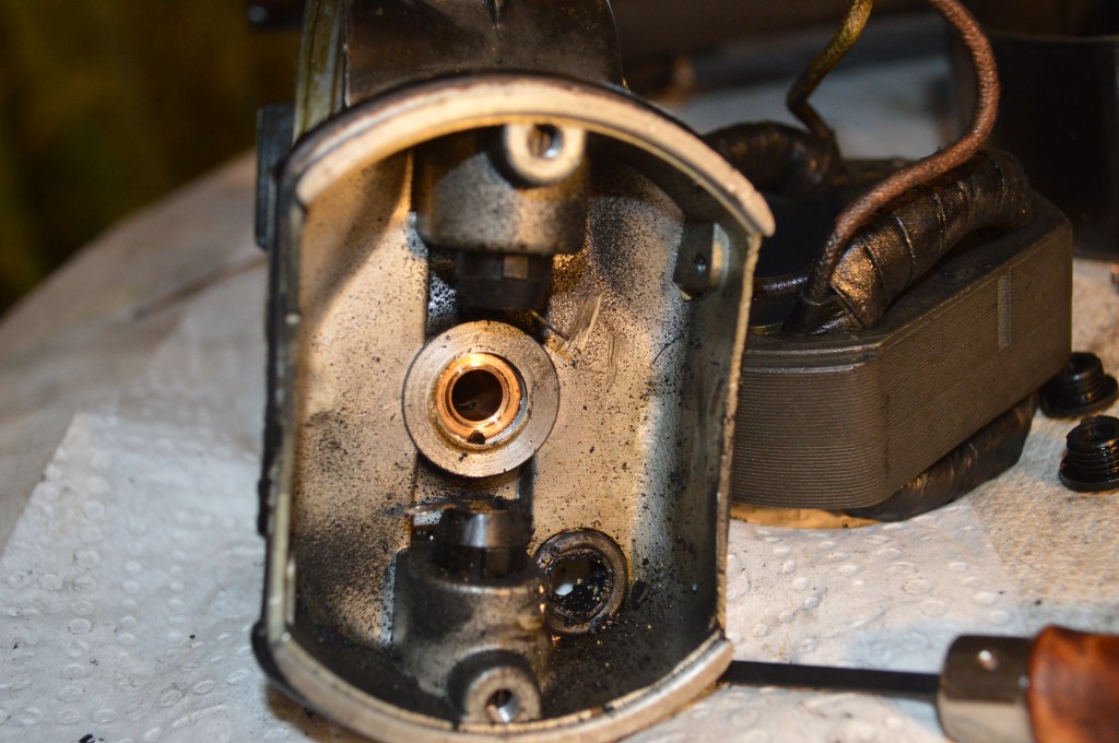
With these wires desoldered, remove the field coil 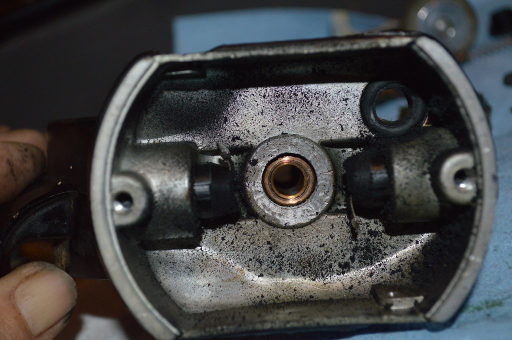
The two recessed screws hold the brush tubes in the housing. Loosen these 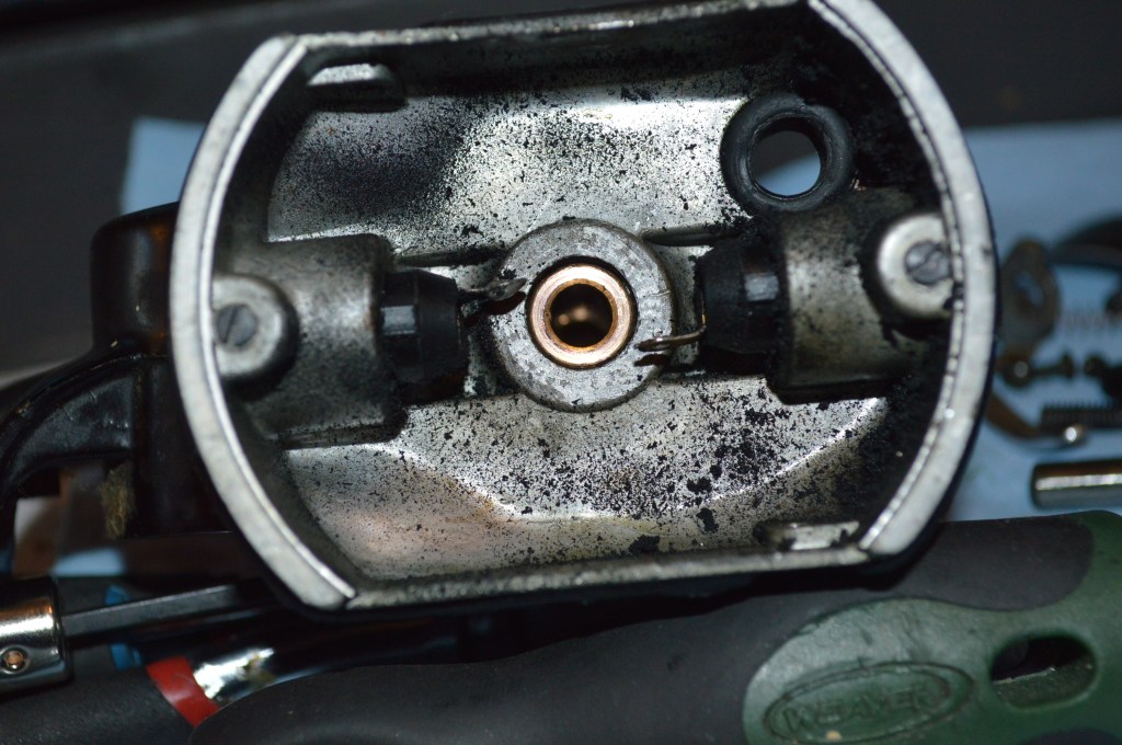
Bend the tabs as shown 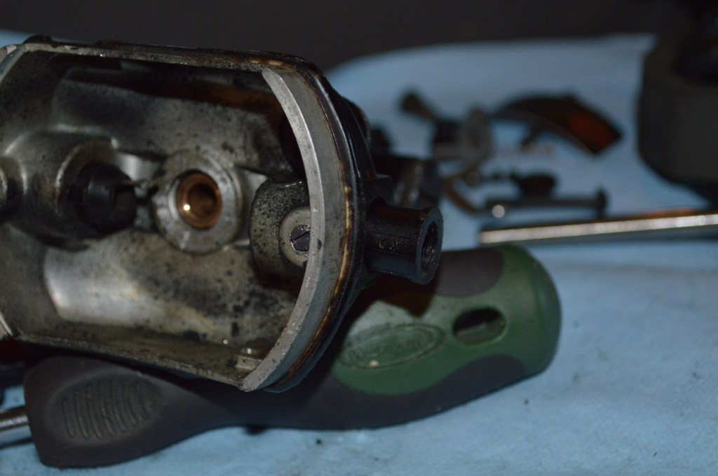
The brush tubes are removed from inside to outside. They should pop out easily
Next we remove the grease wicks.
Remove the grease wick caps 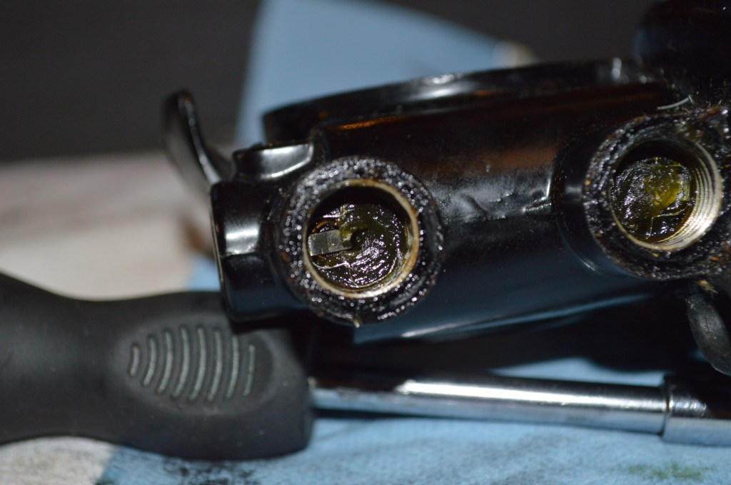
The wicks and wick springs are held behind these retainer clips 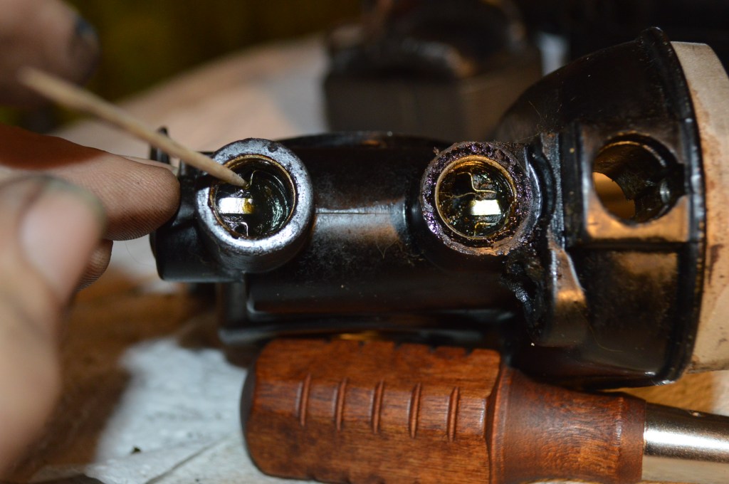
Gently pry at points shown, wiggle the retainer up past the screw cap threads 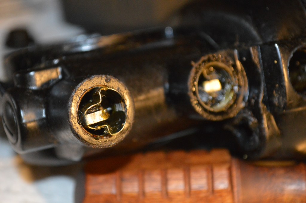
Notice the orientation of the clips… they only fit one way 
Remove the retainers, springs, and grease wicks
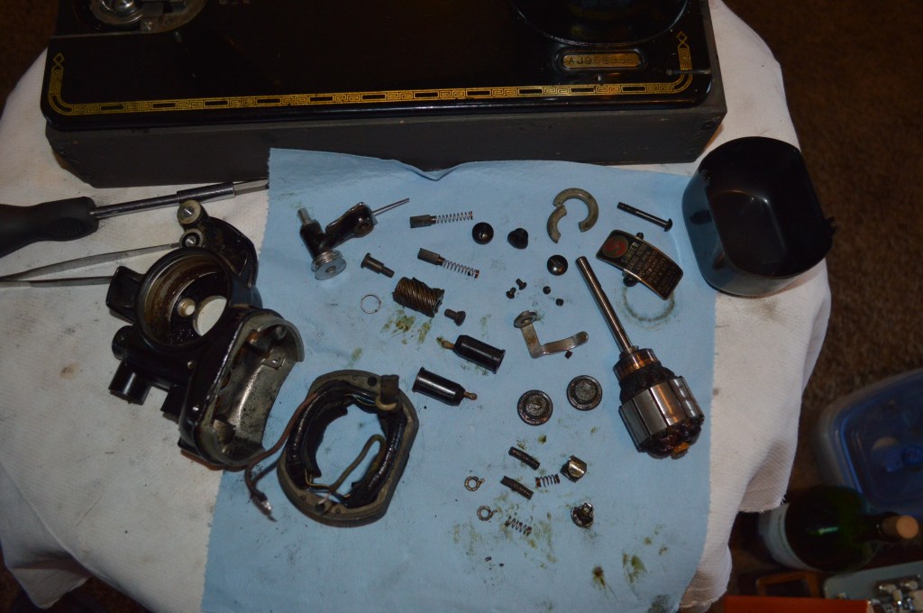
Lay all of the parts out for cleaning and keep track of them… there is a lot of grease and small parts sticking to this grease are lost easily.
With the motor housing stripped, it, the spiral gear, and the grease wick retainers are soaked in kerosene for about 24 hours to dissolve the grease. Kerosene will dissolve the grease without damaging the paint. All other parts except the motor brushes, field coil, and armature are ultrasonically cleaned. They can be cleaned manually.
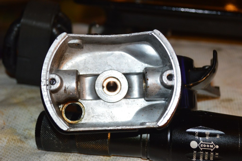
After soaking in kerosene, the motor is cleaned with compressed air and cotton swabs to remove all old grease 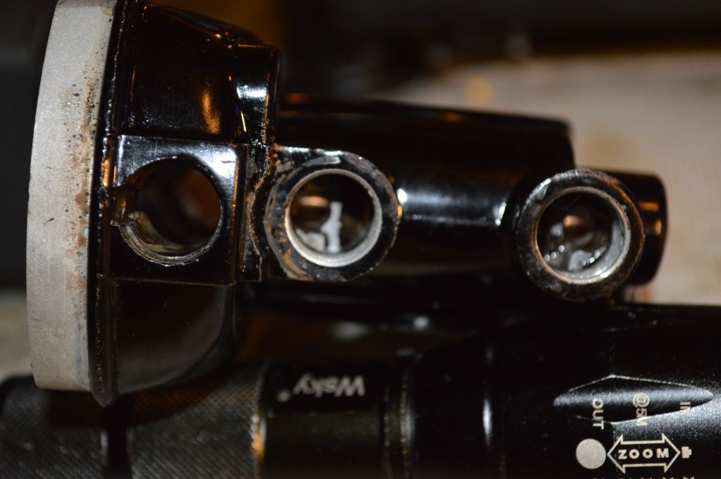
Make sure the grease tubes are cleaned… old grease left here will mix with the new grease… not desireable 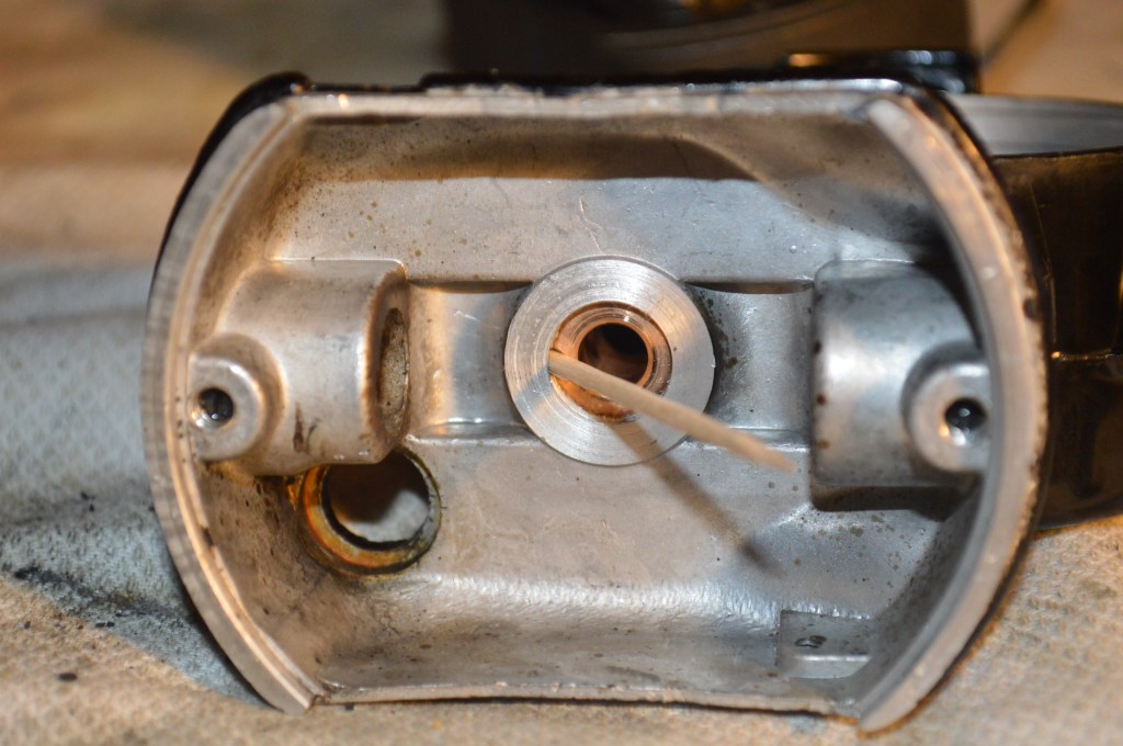
The toothpick shows the location of a grease port in the motor housing. Probe this hole to remove any grease that might be plugging it 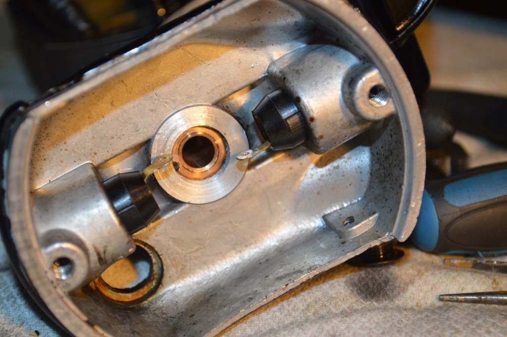
Reinstall the brush tubes 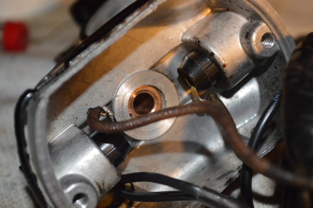
Resolder the field coil brush wires
Next the main wires are replaced… I use solder connectors for ease and a good solid joint. I find it difficult to “twist” the new wires to the old wires… remember the old wires are brittle. I make my own as follows.
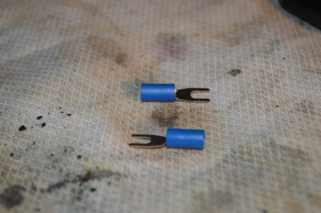
Start with crrimp fittings… 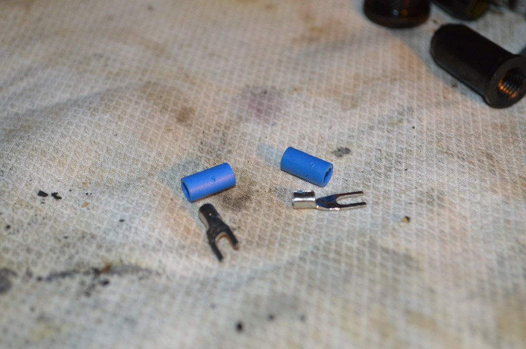
Remove the plastic collars 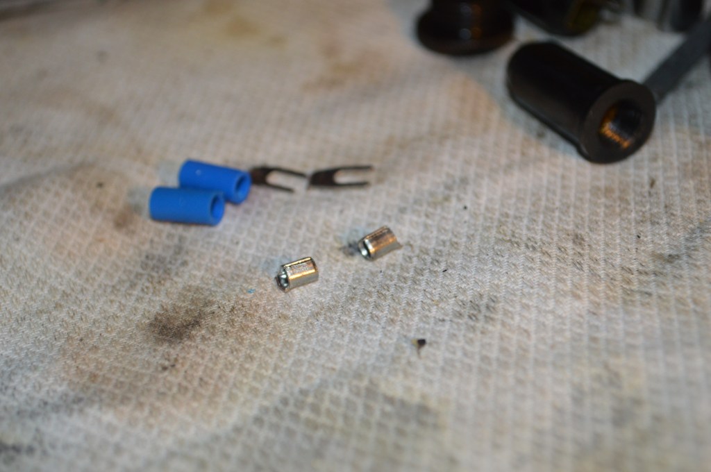
Cut the connector from the crimp connector 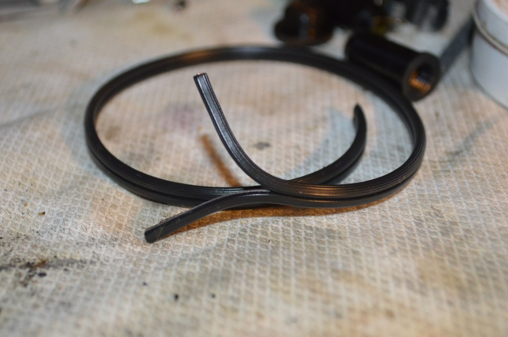
Use 18ga lamp wire and cut it a couple inches longer than the old wires… they are trimmed to proper length later when the end terminals are soldered on 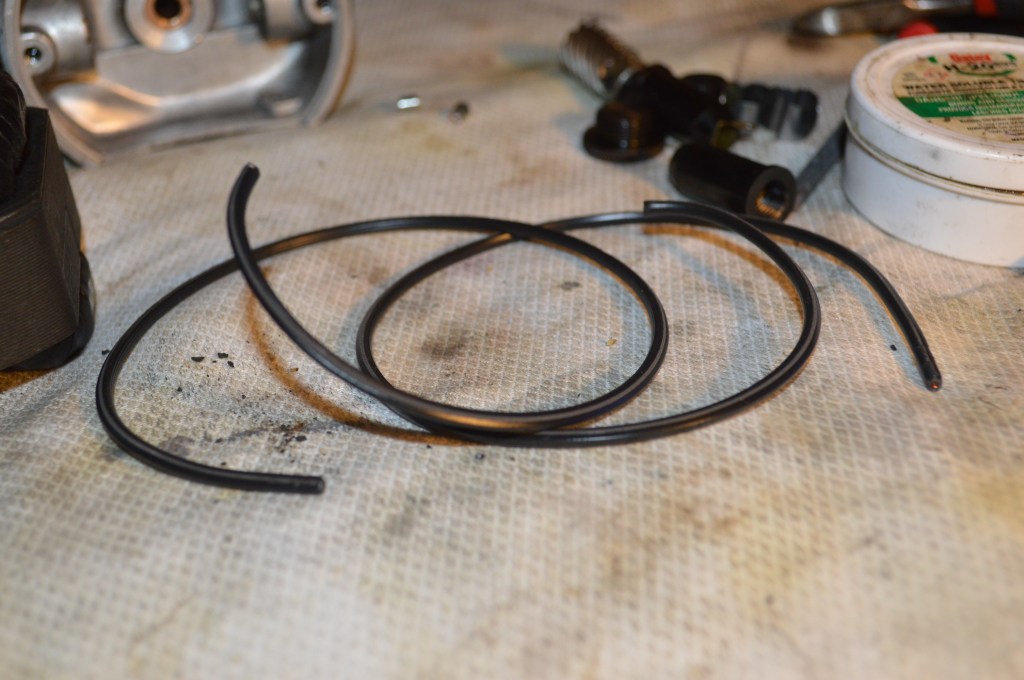
Pull the wires apart and strip the insulation about 1/4″ 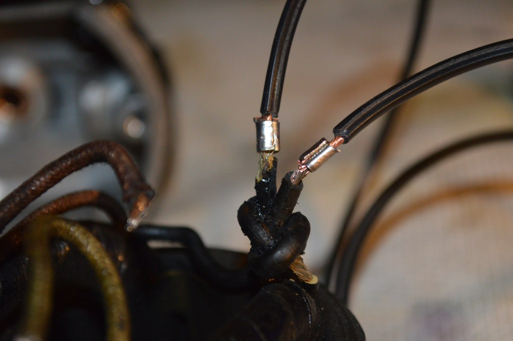
Put the end of the old and new wires securely in the connector and crimp 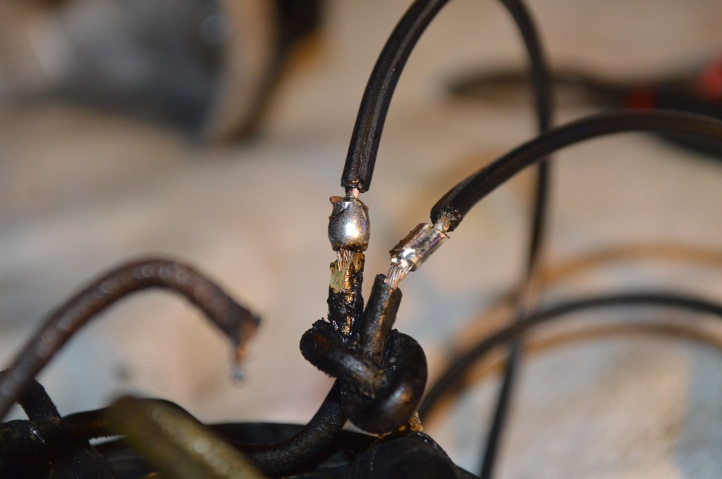
Solder the connector 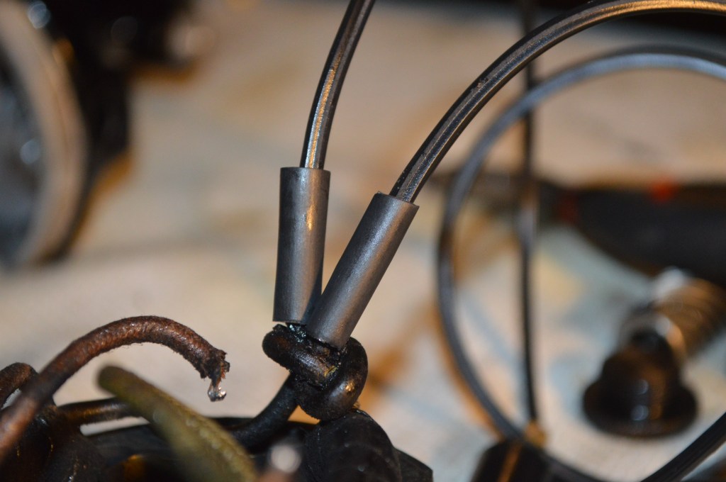
Slide shrink tube over the solder joint 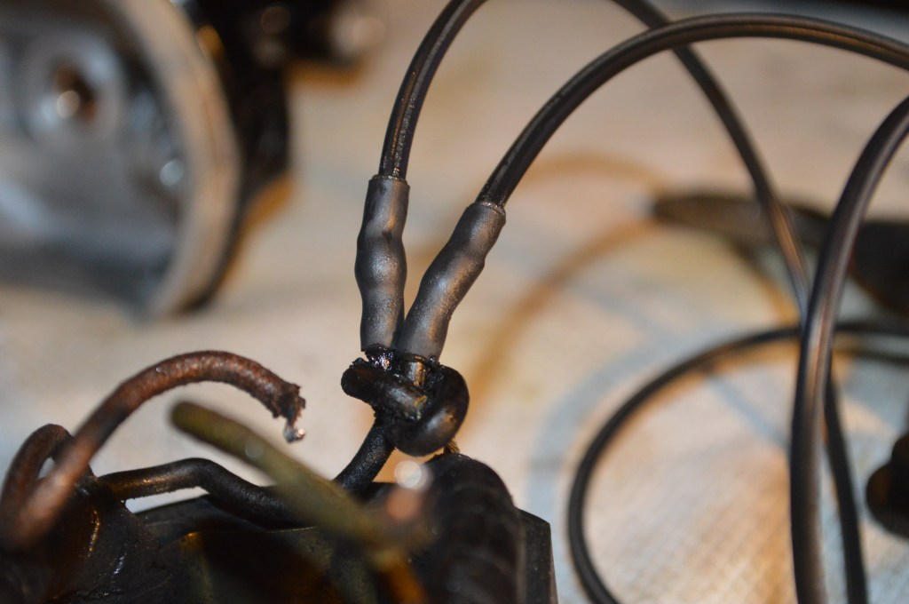
Shrink the tube so it firmly grips the wires… just enough heat, no more. 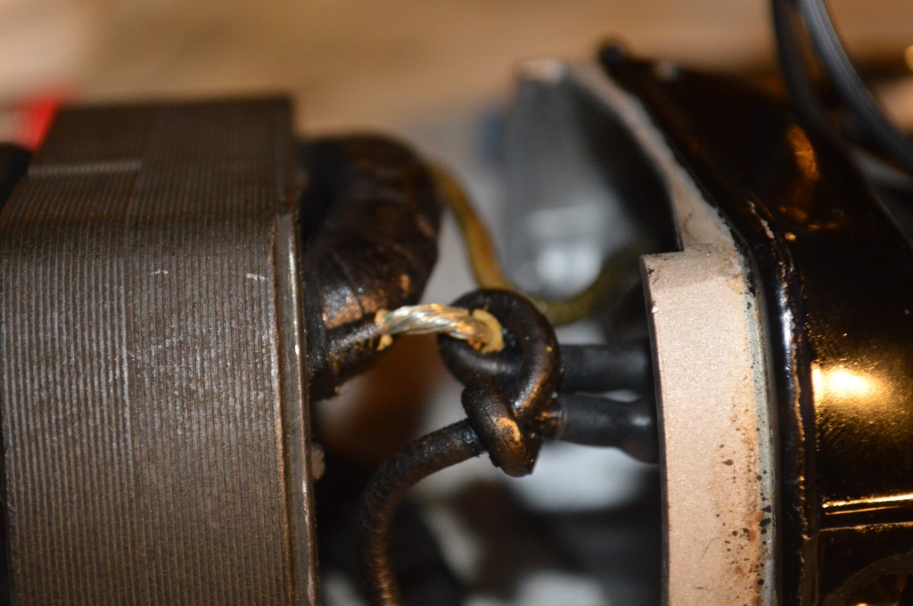
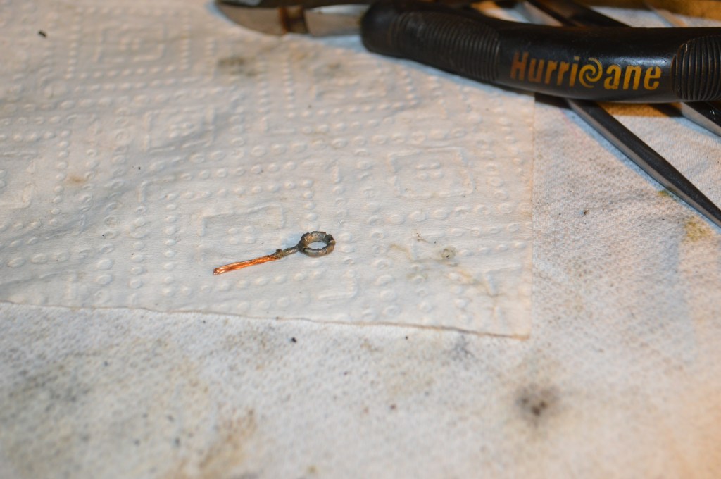
Remember I said the old wires are brittle. They may crack as shown. If they do, they must be reinsulated 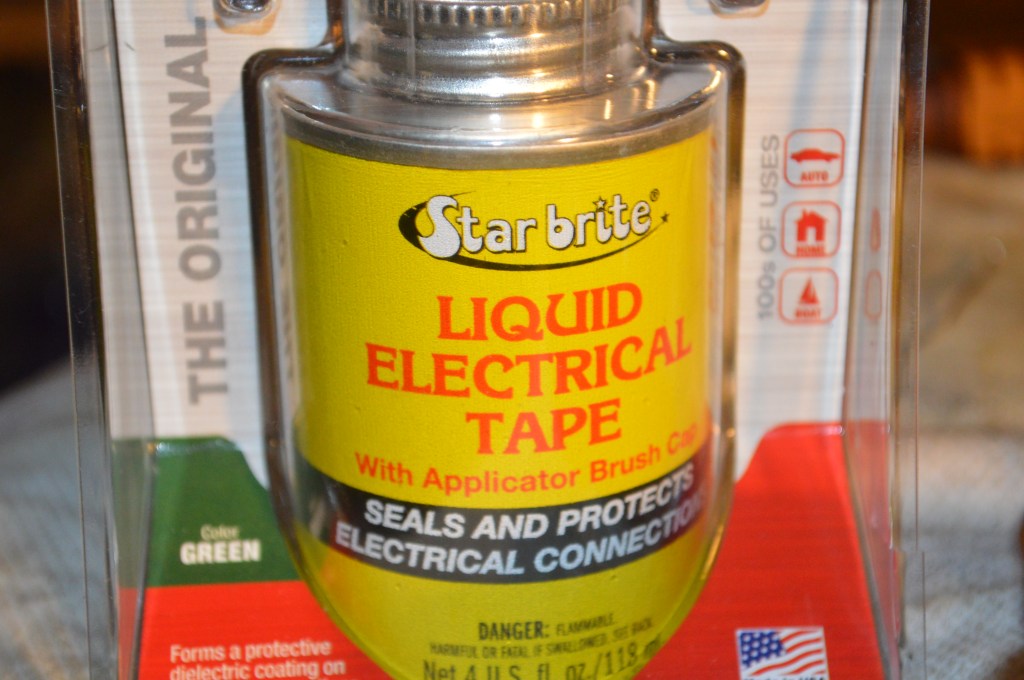
This product will dry into a pliable plastic coating. It is messy but it works great. Coat the cracked wire and the loop with this stuff and let it dry… it’s messy and flows, so apply it with a toothpick, not the brush in the can. Use several coats until the bare wire is completely encased and insulated.
Next, the motor can be reassembled. Remove the old grommet. Make sure the new wires are routed through the grommet hole and gently pull on them as you are seating the field coil. The key is to make sure the wires are not going to interfere with the armature and have clearance in the housing. The commutator and armature shaft is polished before reassembly. I use jewelers rouge on the commutator and 2500 grit wet/dry sandpaper wetted with oil on the shaft. In lieu of jewelers rouge, the commutator can be polished with dry 2500 (or finer) grit sandpaper. For polishing, chuck the shaft in an electric drill and spin it at a moderate speed. Wipe with a clean cotton cloth to remove traces of oil.
Commutator and shaft polished 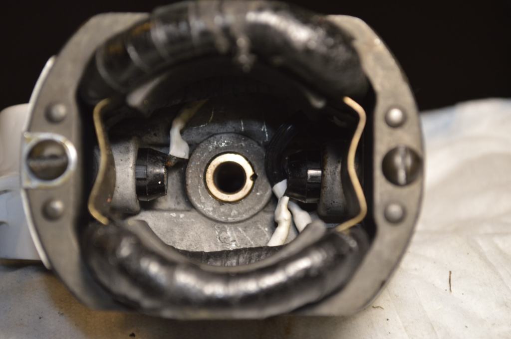
Check for wire clearance and install the screws to tighten the field coil to the housing 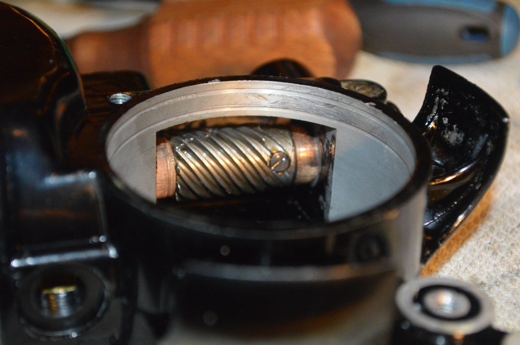
When reinstalling the armature and the worm gear, lightly coat the armature shaft with grease, and make sure one of the set screw tightens on the “flat” groove on the armature. This can be easily done by removing one of the screws and turning the shaft until the flat spot presents itself 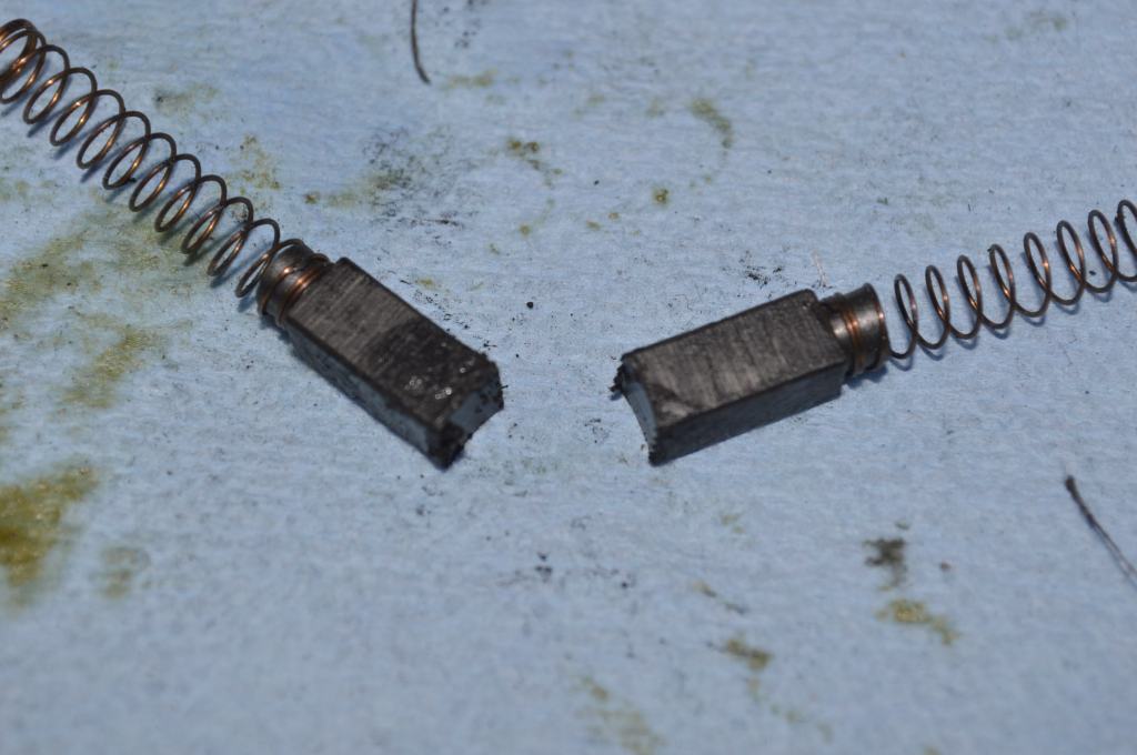
Notice the curve on the motor brush… this is easily reconditioned 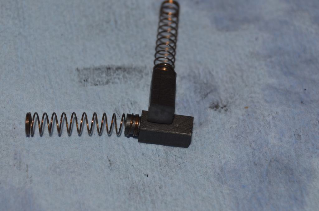
The brush is soft graphite. Use 600 grit sandpaper to flatten the face.
Reinstall the springs and brushes in the brush tubes and gently tighten the bakelite brush caps. They do not need to be tight… snug is good. To much tight and they can break.
Install a new rubber grommet on the motor housing where the wires enter. It is a 3/8″ rubber grommet available at most hardware stores.
Almost there… the hard part is done. Only the grease wicks and end connectors remaining. If you opt not to replace the grease wicks, the old wicks can be cleaned with dish detergent and plenty of water. The cleaned wicks (thoroughly rinsed) can be dried in the oven or toaster oven at a low temp… 170 degrees for an hour or two is sufficient. Keep in mind, cleaning the wick is acceptable only if the wick looks usable, that is, it is still pliable and not hard from the old grease. Also, the wick should not be stretched or rolled thinner. It needs to fit properly in the motor housing.
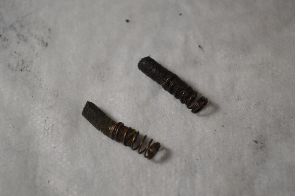
Old grease wick 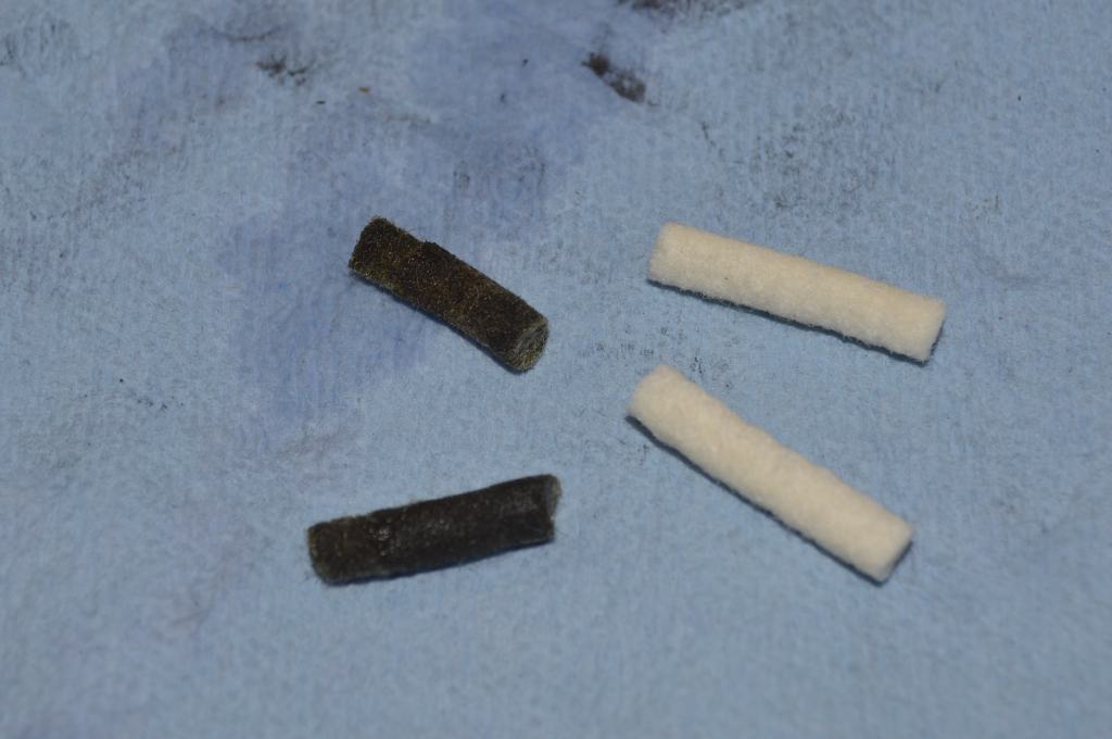
New grease wick, thread into spring about half way 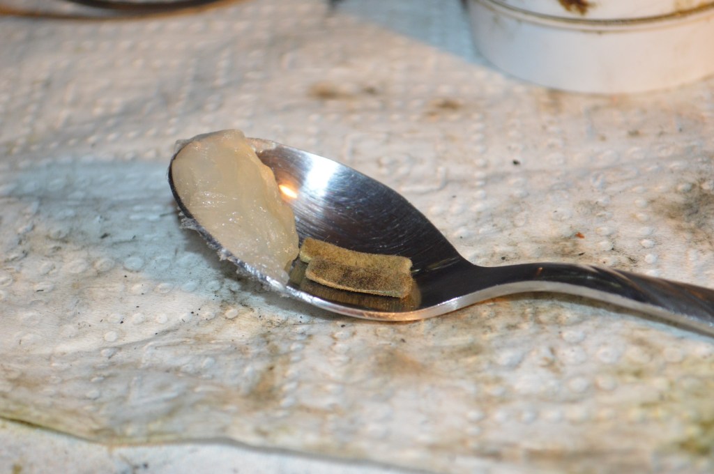
Charge the wicks with grease… 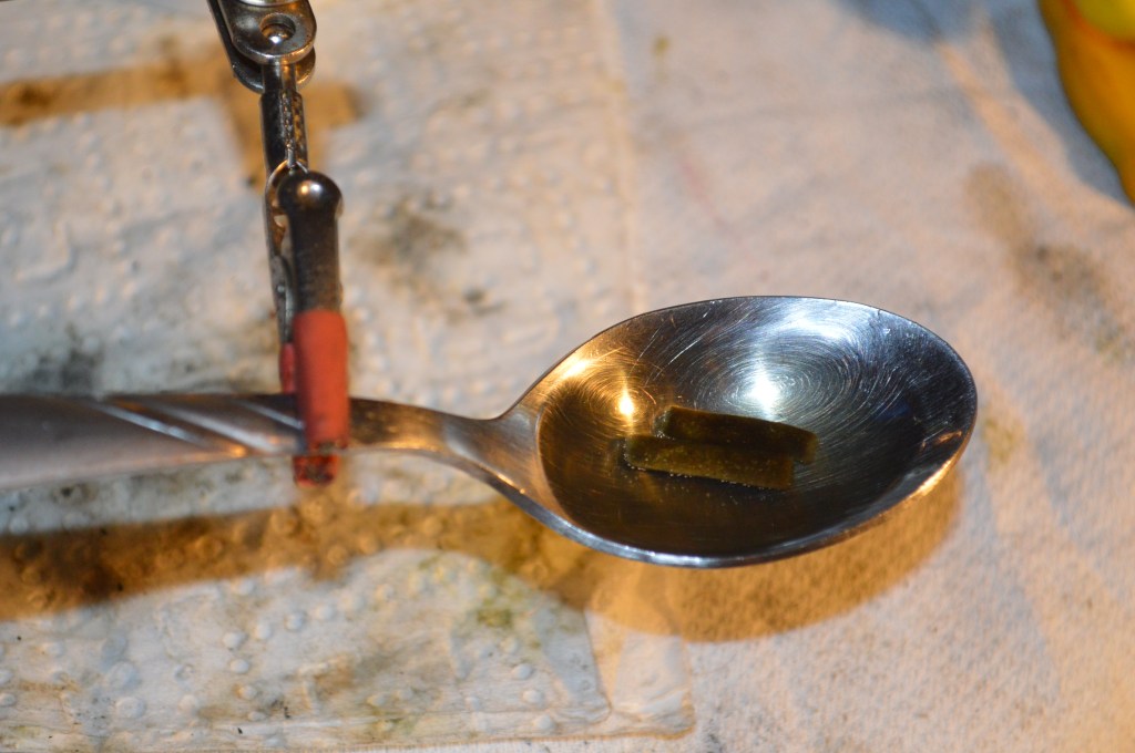
Heat enough to melt the grease and let the wicks sit and absorb the grease as liquid 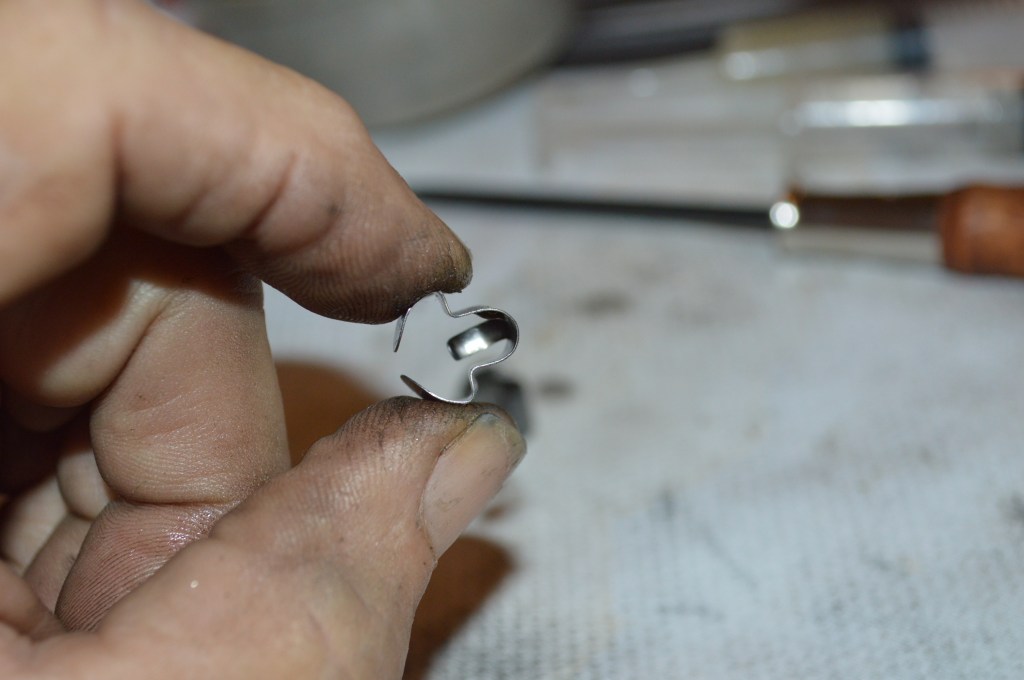
Cleaned grease wick retainer 
Install wicks and retainer. make sure the spring is captured under the tab as shown 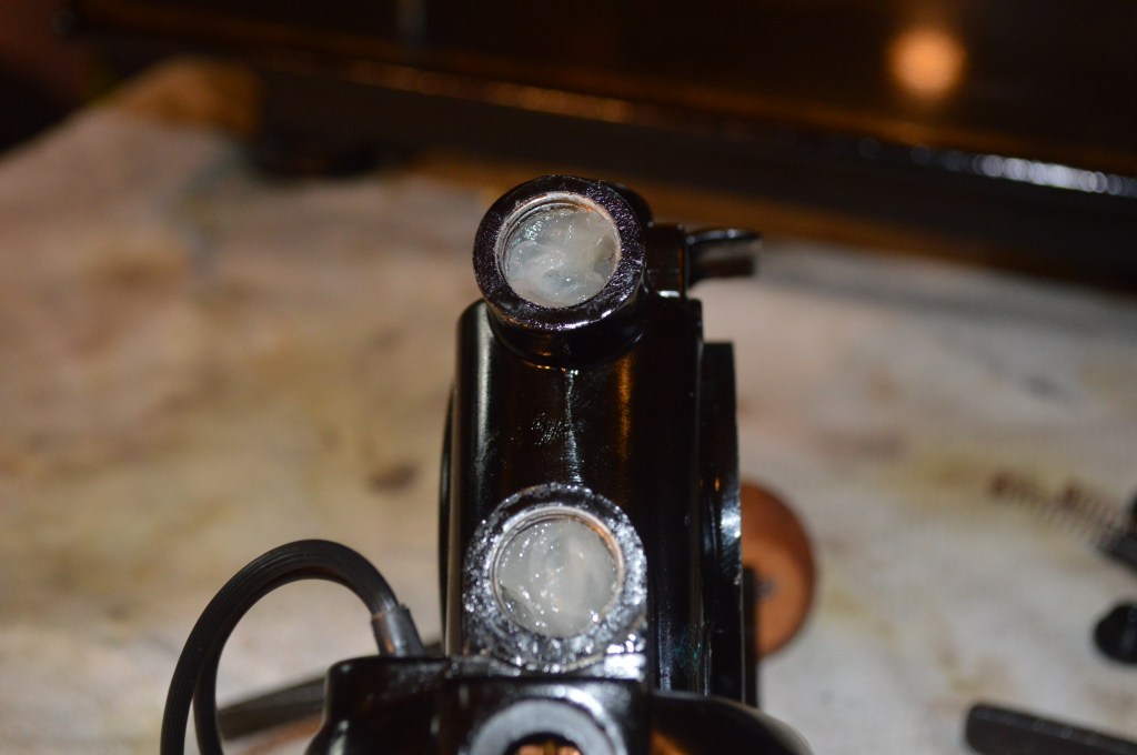
Pack the grease tube with grease… A 10Ml oral syringe works great for filling the tube.
Reinstall the grease wick caps and the armature end cap. Wondering about what motor grease to use? Use 100% unadulterated petroleum jelly… the cheap stuff with no additives. There has been much debate on this… but it has the proper melting point for these motors and provides adequate lubrication. If you are unsure or don’t believe me, research the topic online. I’m not being cheap here, a substitute is necessary. The simple fact is that these grease wick motors have not been produced for a very long time, and the stuff originally formulated for them is not available anymore.
Now trim the new wires for final length. Reinstall the motor on the machine and route the new wires to the wire plug connector. Leaving about an inch or even a little longer is better than too short. The end connectors from the old wires are reused.
Cut connector from old wire and strip all insulation 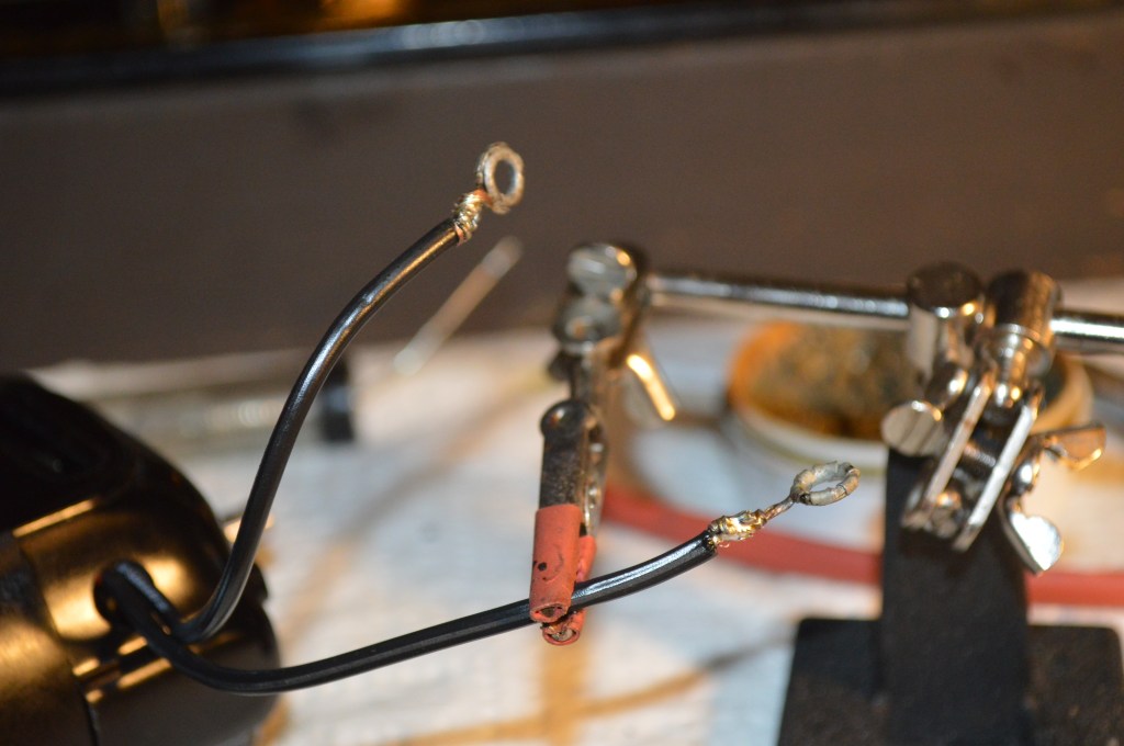
Strip end of new wire and twist the bare wires around each other… solder and then use shrink tubing to insulate the solder joint 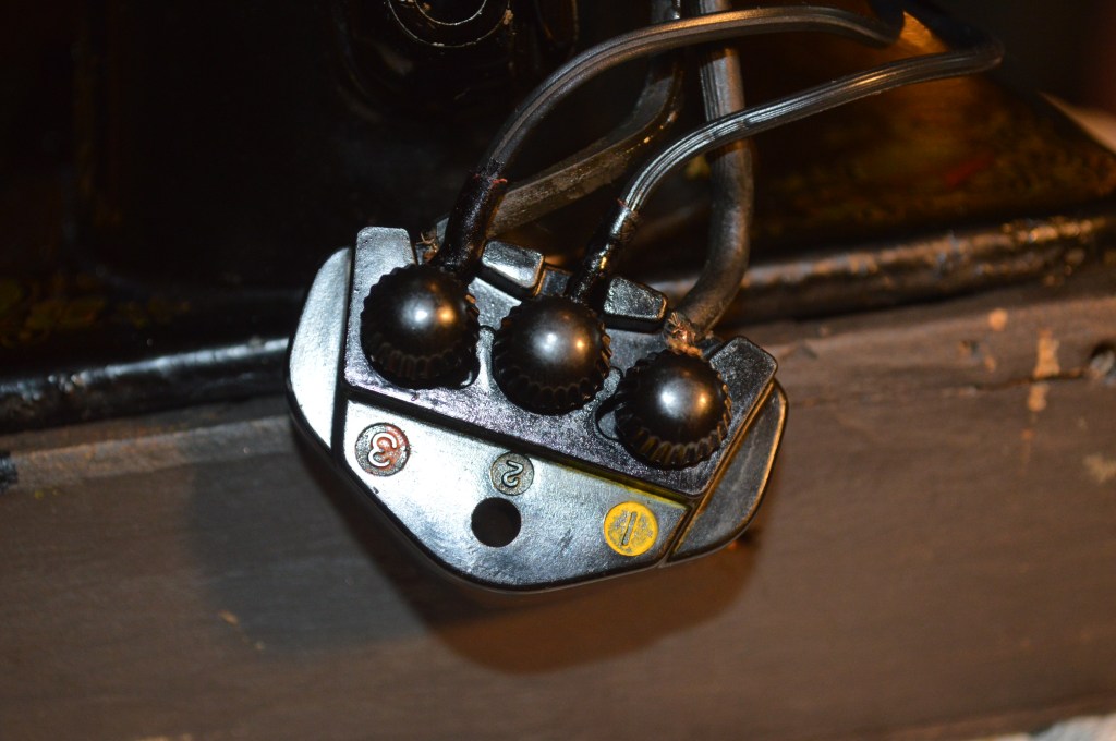
The wires go like this: motor wires to terminal 2 and 3, light wires to 1 and 3. If you are hardwiring the controller, it goes 1 to 2
Coat the worm gear and the textolite gear with a good quality grease. I use Tri-Flow synthetic grease for this purpose. Now would be a good time to restore the shock absorbing mechanism behind the textolite gear. It is not hard and you are halfway there with the balance wheel off. Its easy and takes about 15 minutes. See my blog showing how this is done at:
If you choose not to do this now, you are done!
Now the motor has been restored, it is important to “run it in”. This simply means run the motor on the machine with the sewing mechanism disengaged… Run the motor at full speed. You may notice that it runs slower and then faster. This is okay. Keep running the motor until it picks up speed. You will hear the speed increase. Run the motor until the end cap starts to feel warm to the touch. Alternate the speed from fast to slow. The purpose here is to seat the brushes and wicks. As the motor warms, the petroleum jelly will melt, fee the wicks, and lubricate the shafts. The motor will break-in after some use and you may notice some increase in speed. All of this is normal, and the motor should be good for another few decades!
That’s it! Your patience and attention to detail will pay off if you choose to restore your motor, I hope that this tutorial has helped you and answered a few questions in the process. Don’t hesitate to contact me if you have any questions, and please visit our Etsy store at https://www.etsy.com/shop/pungoliving, to see our restored fine high quality sewing machines.
As always, our tutorials are provided as a free resource to help you learn and maintain your vintage sewing machine. As our site has grown, so has the cost to keep and maintain it. Despite these costs, I will strive to continue posting tutorials and other relevant content for the benefit of the sewing community. If you found the content of this tutorial useful, please consider making a small donation to help me grow the site and help defray my costs… every little bit helps.
Help Support our Site…
Make a one-time donation
Make a monthly donation
Make a yearly donation
Choose an amount
Or enter a custom amount
Your contribution is appreciated.
Your contribution is appreciated.
Your contribution is appreciated.
Please let me know if you have any questions or if I can be of any assistance!
Thanks for reading!
Lee

I am restoring a singer 101-12. Same as the Singer 101-4 except that the heavy parts are made of aluminum reducing the weight of the machine, (although it’s still crazy heavy). And it’s in a portable case.
I am working on getting the motor to work. It seems to be seized but not totally certain of what is wrong. I am only finding instructions on the potted motor for15-91 and 201-2. This motor is slightly different than mine. Do you have instructions for taking apart and servicing the 101 potted motor?
LikeLike
Hello Kelly.
The 101 has a “potted motor”, but it is not the same as the potted motor on a 201 or 15-91. I happen to have 2 of these machines, both 101-12’s and I was planning a restoration for one of them. I will take a good look at the motor in the next few days and plan a tutorial around it…
BTW, the 101 is what I consider a fairly uncommon machine, less than 250,000 were made in a fairly short production run. They are unusual in their oiling system but make a fine stitch.
I will let you know what I can do about a tutorial!
Thanks, Lee
LikeLike
Oh that would be so wonderful! The problem I seem to be running into is that the motor seems to be seized and I am hoping that there is a way to get it unseized. I enjoy your tutorial greatly. I have a mechanical mind and you take such care to explain in detail. It’s very easy to follow.
I know that it is different than the 201 and the 15-91. I was trying to work around that. I have a 15-91 that I love.
I actually think that the 101 potted motor might be a little easier in some ways.
I’ve also discovered that it is rare as I am having a hard time finding info on how to fix them. 🙂 But I am so hoping to get her working!
LikeLike
I have a 201-2 Singer in need of repair. Love this tutorial, but it doesn’t quite address the problem I have. The main wires that go into the windings have broken off inside the windings. What is the best way to proceed?
LikeLike
Good afternoon Amy,
If the main wires have any length available to attach new wires, there may be hope. If they are broken too deep into the winding, it may not be possible to solder new wires without melting the thinner coil windings.
If you can send me a picture to pungoliving@gmail.com, I may be able to give you an idea on how to proceed.
I hope this helps!
Lee
LikeLike
Hello Lee
I have 4 Singer 15-91’s that I have acquired in the last month all have the potted motors. I am rebuilding them one at a time. The first one I took the balance wheel off to find a nightmare. Someone had this apart before and one of the screws had a stripped out head. After few hours of drilling going very slow I was able to get the head off the screw. I was able to take the motor off then used a Dremel with a cutting wheel to make a slot in the stud that was left from the screw and removed it with a screwdriver. I have to admit I did use a few choice words getting this done. Now I am rewiring following you wonderful tutorial thank you very much for this.
I am retired Marine Corps veteran and taking this up a hobby. I have been watching many You tube video’s ect and reading all I can to learn how to work one these wonderful machines. If I need to do a total replacement motor on any would you advise to replace the Balance wheel with a belt driven wheel and motor? If so where can you find the wheel or can you use like a 99 or 66 wheel on this machine?
My wife is also a sewer and quilter. She has two Long-arm machines one in the dining room the other in the living room.
LikeLike
Hello Ed,
I’m glad you found some useful information.
I don’t think you have too many options for motors on a 15-91. The potted motor incorporates the bobbin winder and the spacing of the motor will not allow a good fit and result in a large gap.
The key to removing the motor screws is to use impact… tap on the screwdriver as you are trying to loosen them. I haven’t tried a 66 balance wheel on the shaft, but if it is the same diameter it would work… personally I would replace the potted motor. If you do replace the motor, make sure it is a potted motor from a 15-91. the bobbin winder is different than on a 201 potted motor (class 15 vs class 66).
Let me know if I can answer any questions, I’ll be happy to help.
Have a great day!
Lee
LikeLike
Where can I get the new wicks and is a greased wick in the screw end of the commuter shaft just outside of the worm gear? How far does the shaft go in? I noticed it can reach the screw.
LikeLike
Hello Debbie,
You can buy replacement wick for the 201 on Ebay. They are essentially cut to length but some trimming may be necessary.
Once you remove the old wicks and clean the old grease out of the grease tubes you will see that the wicks are guided in place by a bore in the motor casing at each grease tube. The wicks are not installed until after the commutator shaft and the worm gear are re-installed. You will see that the worm gear has 2 set screws. One of the set screws tightens against a flat milled in the commutator shaft. The commutator shaft is inserted full depth and bottoms out in the motor case… you cannot tighten the worm gear on the shaft until it is fully seated. It is not difficult to insert the shaft and you will know when it seats. If the pictures don’t show enough detail, let me know how far you are in the restoration and I will be happy to clarify any questions you may have.
I hope this helps!
Lee
LikeLike
Hey Debbie, This is so cool. I have been looking for a restoration of a 101-4 or 101-12 motor. I have a beautiful 101-12 but the motor seems to be seized. I have done what I can but my skill is lacking. Do you have a motor for this machine or have a tutorial for restoring one??
LikeLike
Hello Kelly,
It’s a small world! I was thinking about a 101 just a few days ago. I also have a 101 with a motor that needs a restoration. It’s not seized, but it is not powerful. I was actually thinking about making this machine my next restoration.
The 101 is an unusual machine and much different from most machines of it’s vintage. If there is anything approaching a “rare” Singer sewing machine, the 101 would meet the definition by my standards since only about 264,000 were manufactured. If you would like,
I would be happy make it my next tutorial and let you know when it posts!
Have a great day!
Lee
LikeLike
Yes thanks! I’d be interested too. I cant get my wheel off to clean behind even tho I loosened the set screws inside on the horizontal shaft.
LikeLike
Hello Debbie,
There are tutorials on Youtube from folks (not me) showing how to remove the motor… the motor is attached by the screw on the front of the pillar. Be careful trying to disassemble this machine. The design of the 101 is different from all other Singers. There are clutch discs behind the balance wheel that must be in a certain order. I expect my tutorial will cover this and other assemblies. If you would like a copy of the adjusters manual, please email me at pungoliving@gmail,com and I will send you a copy.
Lee
LikeLike
Lee and Debbie, Hello. I’m so glad to find other people that have a 101 as I have not had any luck with anybody that knows anything about them thus far!
I found it easy to remove the motor, although you need to take it slow and careful.
I would love, love, love a tutorial about refurbishing the motor and I’m also interested in purchasing a motor already refurbished as I don’t know if I can get mine unseized.
LikeLike
Good morning Kelly,
I see 101’s come up for sale occasionally. We have two… one in excellent cosmetic condition and the other in okay condition. It’s the one I’m planning to restore.
I see parts come up on Ebay and you might find a motor. The motor you have may run great after a restoration as long as the motor windings are good.
I can’t attach files from WordPress but send me a message at pungoliving@gmail.com and I’ll be happy to send you the adjusters manual.
Have a great day!
Lee
LikeLike
Yes pretty please. I would love the adjusters manual. But a visual tutorial would also be super.
LikeLike
Great! I’m planning the restoration now. Email me at pungoliving@gmai;.com an I’ll send you the manual.
Have a great evening!
Lee
LikeLike
Can you explain what work you done to the commutator as it looked as if it was worn to the point of needing machining and then re-slotting.
LikeLike
Lee. Thanks for your help. I have just rewired/rebuilt my second potted motor. I have two 201-2 Singers and will pick up a third next week. I need to know the direction of rotation of the motor looking at it from behind. The last motor I built had no insulation and runs well but without knowing the rotation I might just have soldered the wires in reverse. Help appreciated. I too went through an apprenticeship at NAS Quonset Point as an aircraft mechanic. The base closed soon after and I trained as a welder for the new tenant Electric Boat. Spent the next four years as a welder/instructor then 16 years working for the Supervisor of Shipbuilding in Groton Ct in quality control. Twenty years Civil service which ended in Charleston S.C. but too young to retire in 93. My path followed yours so closely it’s incredible. Bobby
LikeLike
That inside-out motor is pretty cool! Now that I see how it works I can see a couple methods for retrofit. All ya gotta do… is make a replacement shaft and a bracket and couple on either another motor or a pulley for a belt to another motor. While many things seem highly unlikely, anything is possible…even rewinding the armature (it didn’t just fall off a tree).
Ooo… a brushless motor might just fit inside the pot. Mmm…stealth.
LikeLike