

First introduced in 1933, the Singer Model 221 and model 222 sewing machines, affectionally known as the “Featherweights”, are as iconic as they are adored my many, many people. At a mere 11 pounds, it is a “half size” machine. It’s gear driven full rotary hook sewing mechanism is belt driven by an external 0.4 amp motor and it is capable of a fantastic straight stitch. It looks small, but it is not a toy… it is a very fine high quality sewing machine for any sewing task that is not limited by the featherweights limited harp space.
This tutorial is intended to show in some detail how to restore the motor on this fine machine. I often get questions from folks on “how do I” or “I’m trying to” do something to their sewing machine. Often in reference to one of my blogs that showed the same or similar machine completely disassembled and restored. For my part, I am glad to answer questions and correspond with folks who are interested in making their machine sew to their full potential. While I don’t recommend that everyone tear into and disassemble their Great Grandmother’s Singer to the extent that I tear into a vintage Singer sewing machine, there is much that many folks can do with little risk of a disastrous outcome. While disassembling a motor has it’s share of risks, it is one of those things where you can do as little, or as much as you want and see a noticeable improvement when you are done.
Because this is a tutorial, I am going to show you how I do it with the tools that I have to do it with. Knowing that most folks will not have access to all of these tools, I will explain a work around to get satisfactory results to restore the performance of an anemic motor with a few inexpensive items available at most “big box” retail stores and all hardware stores. You don’t have to follow all of the steps, and can follow only the steps you feel comfortable with… in the end you will be better off than where you started.
Ready to begin, let’s start with disassembly. The motor I am restoring is actually in pretty good condition. It is clean, it runs smoothly, but it is a little short on power. The person I’m restoring it for noted a knocking sound at full speed. A restoration on this motor is a perfect opportunity to find out why and to present this tutorial to you if you want to try this yourself.
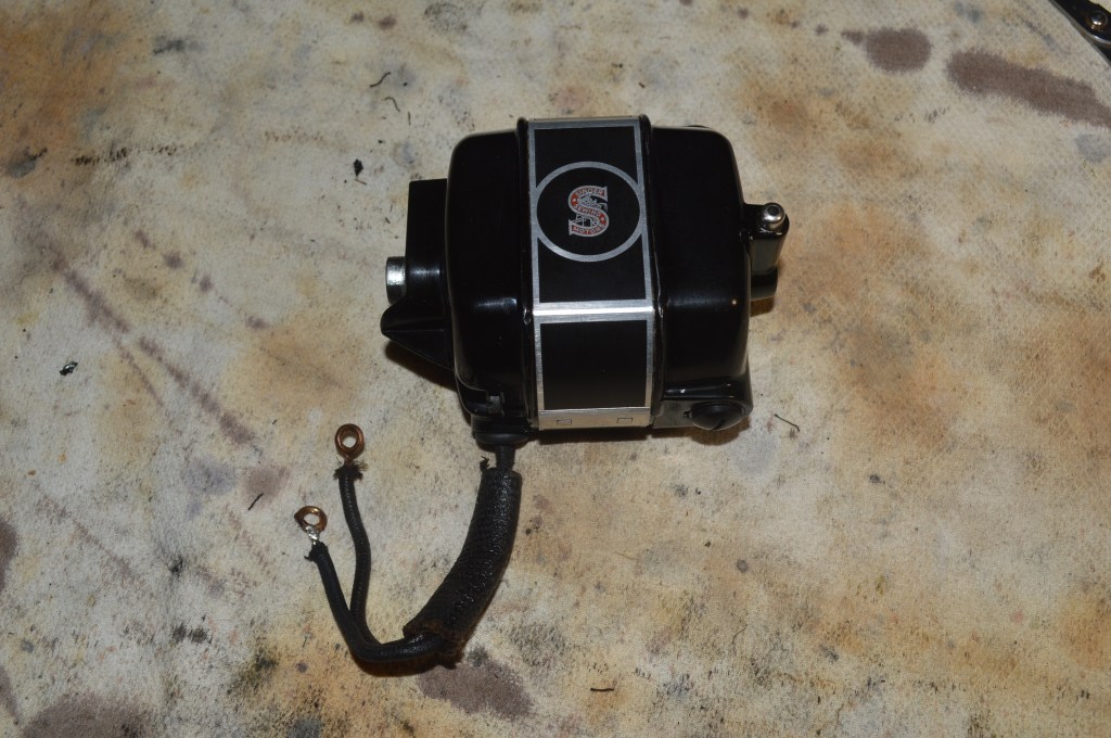
Here is the motor before restoration…
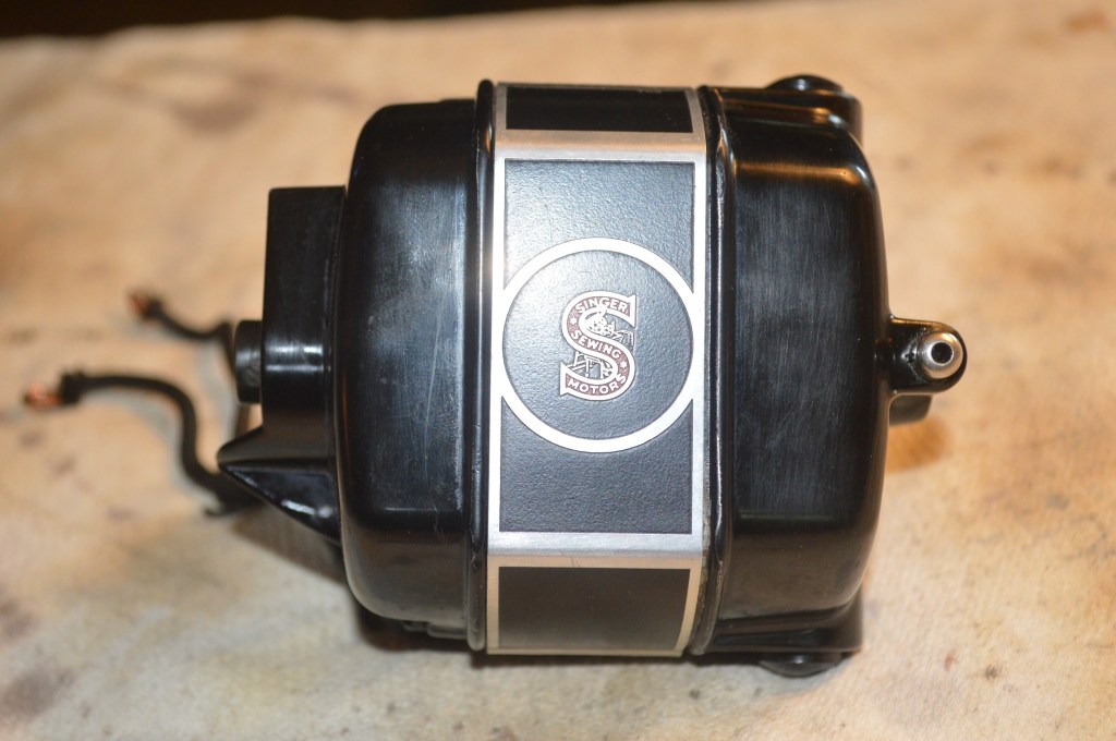
It’s beautiful! Looks like new on the outside but like anything 81 years old, this is not the condition you would expect to find inside. Think about that for a minute… this motor is 81 years old and it is ready to work as well today as it did then… nobody builds quality like this anymore.
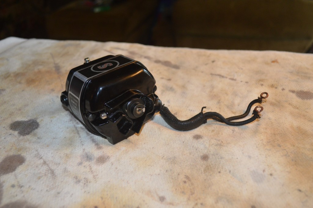
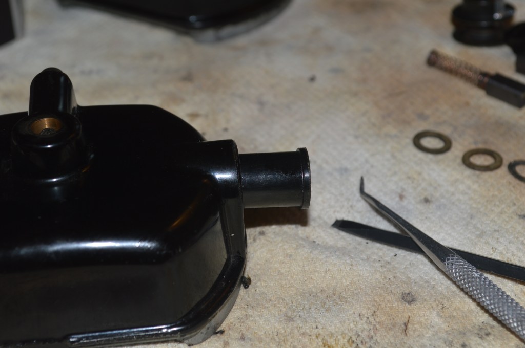
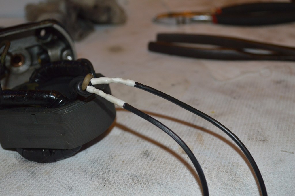
The wires are in very good condition… This is unusual for a motor of this vintage. Even the rubber grommet for the wires to pass through going into the motor housing is still supple and in good condition. This is a great start. In my opinion, it is always better to leave good condition vintage wires alone. They have characteristics that can not be replaced and for this reason, I am not going to replace them. For the purpose of a complete tutorial, I will show the wire replacement procedure on another motor to show how it is done.
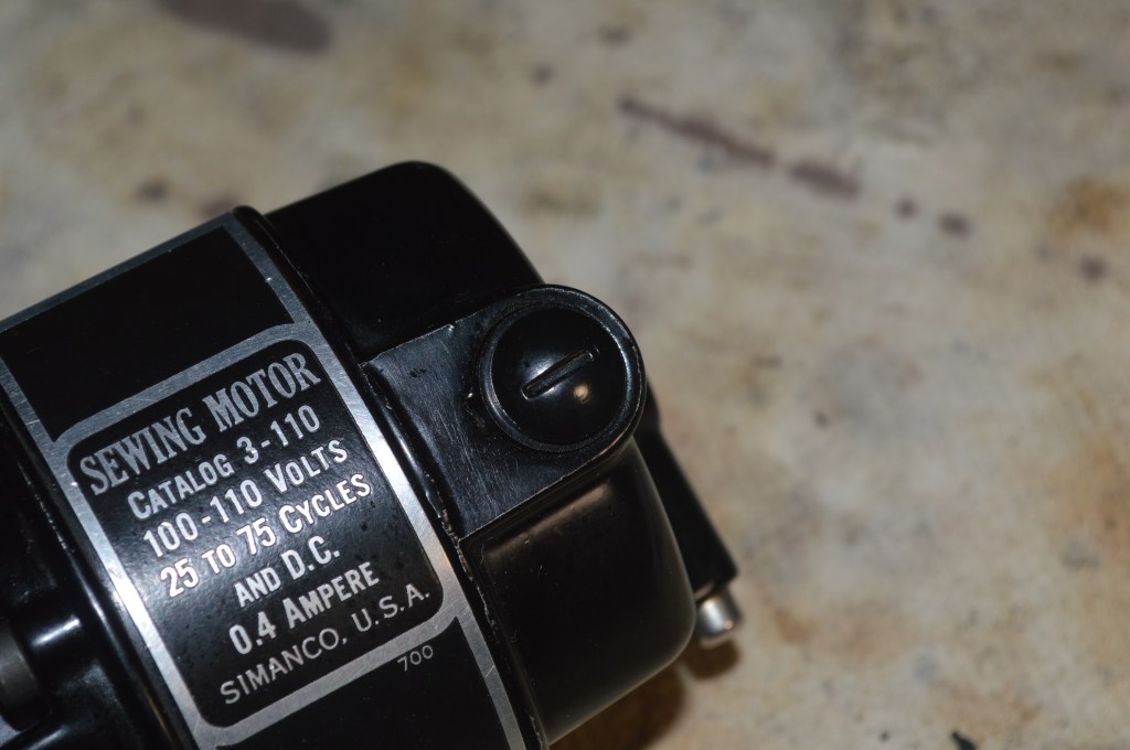
The first step is to remove the motor brush caps. There are 2 of them on opposite sides of the motor. They are fairly brittle “bakelite” plastic and need to be removed gently with a well fitting screw driver.
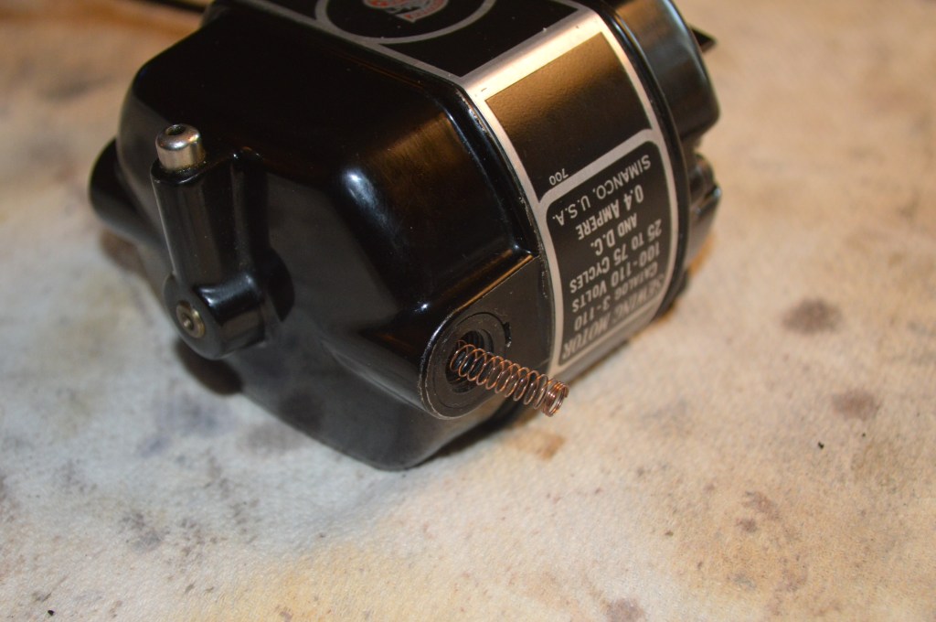
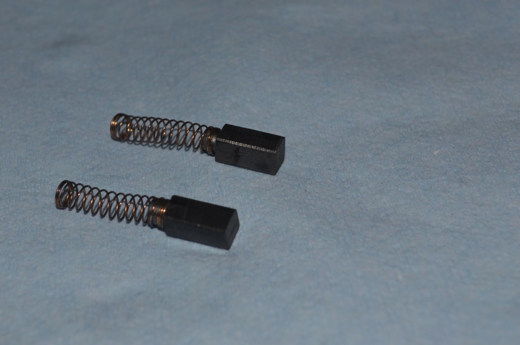
Once the caps are removed, the spring under the caps will release the spring tension and pop out as shown in the picture… be careful that they do not pop out and fly across the room! The brushes are attached to the spring and should pull out easily. If they don’t, don’t worry, the brush can be removed further in the disassembly.
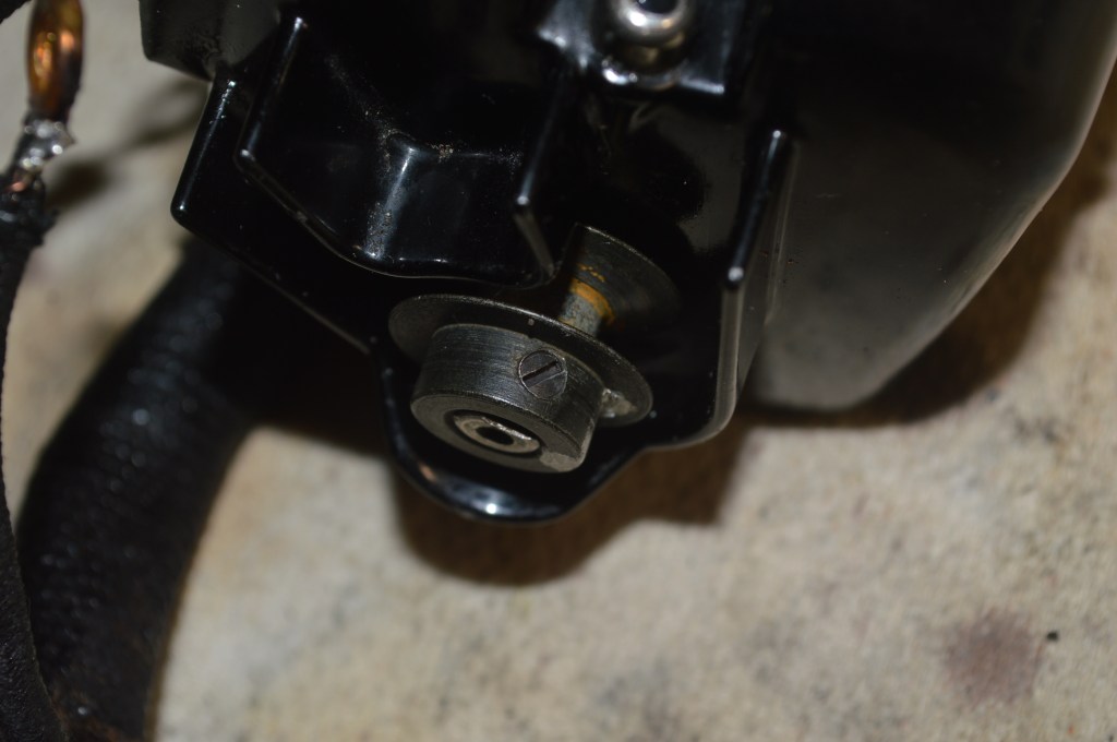
The next step is to remove the motor pulley. Loosen the small set screw that hold the pulley on the shaft. Notice that the shaft has a “flat” ground onto it and the set screw tightens against this flat.
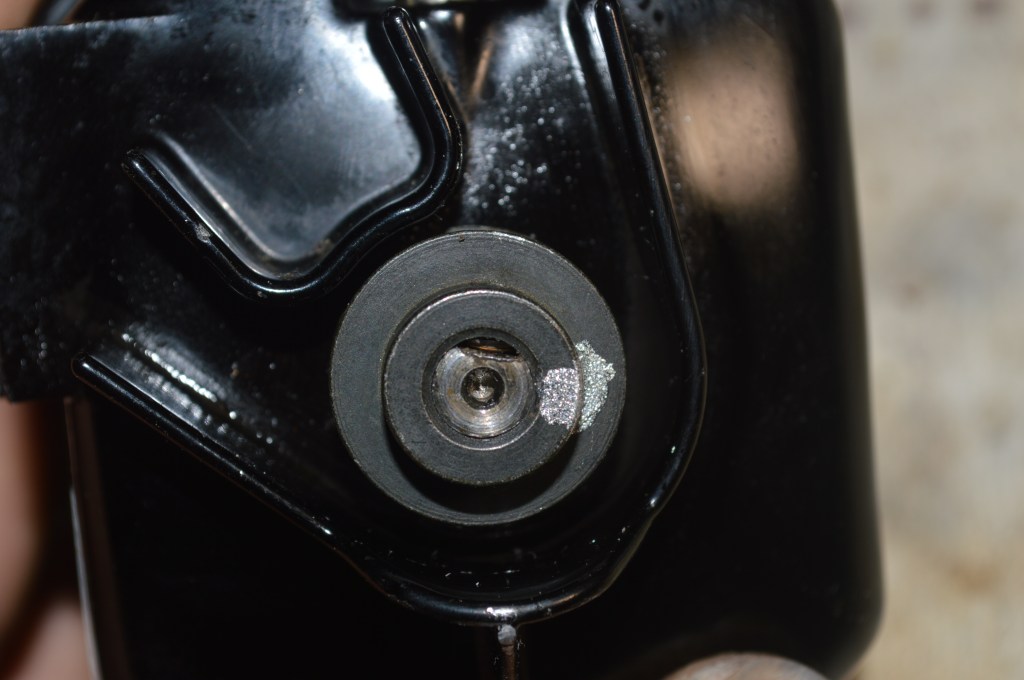
Looking at the pulley end of the motor, the motor case is held together with 2 screws. Remove these screws.
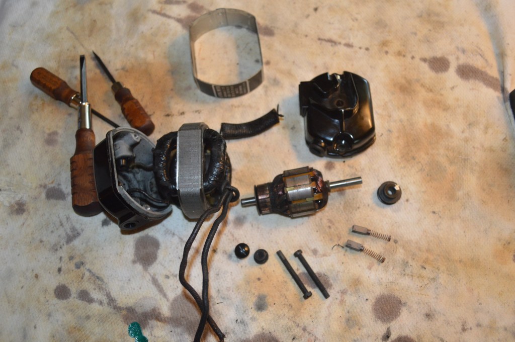
With these screws removed, the case halves can be separated. There are 3 pieces to separate… the front bearing cap, the middle field coil, and the rear bearing and motor brush cap. You will also notice that there is a decorative cover over the field coil. This simply slips over the field coil, but note the direction so you put it back on in the correct position. Take pictures of each piece and the orientation of the wires, grease tubes, and grommet so you will not wonder which end is up when you reassemble everything (trust me on this). It is not difficult to separate these pieces and they can usually be wiggled apart, or gently pry apart from one another with a thin blade screwdriver.
Starting from the front, the end cap is gently pulled straight out away from the field coil. You will need to push feed the wires through the grommet as you remove the cap because these wires attach to the middle piece (the field coil). Do not pull against the wires as this may damage them. As you are pulling the cap straight out, the motor shaft will pull out of the end cap bearing. Now, push the wires completely through the grommet.
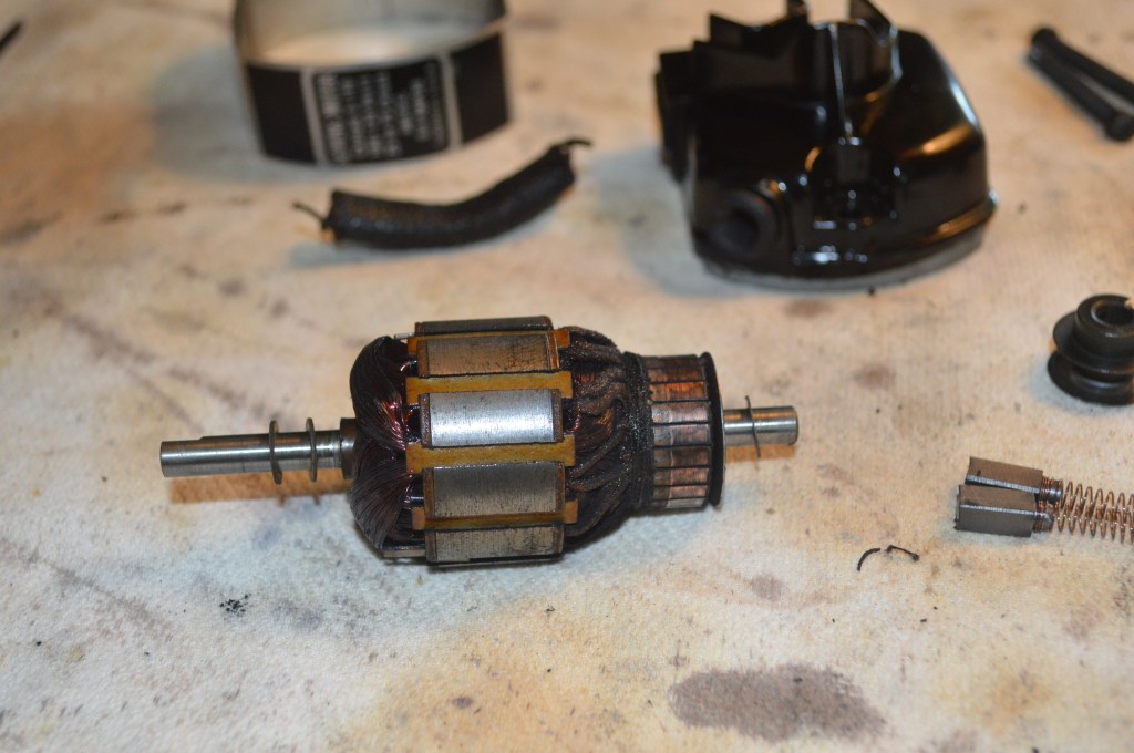
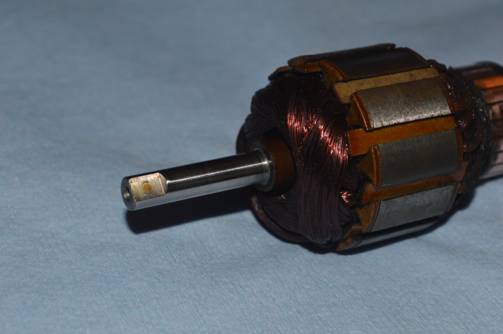
With the end cap removed, remove the armature shaft by pulling it straight out through the field coil. If you were unsuccessful removing the brushes earlier, they will fall into the housing and can bet retrieved when the armature is removed. IMPORTANT!!! there are washers on each end of the shaft that MUST be reinstalled for proper clearance. Take a picture of the armature shaft of these washers so you can remember where they go.
With the armature removed, the rear bearing cap can be removed. Word of caution here… There are 2 wires from the field coil that are soldered to the brush tubes installed in the rear cap. Unless you feel comfortable de-soldering and re-soldering wires, you will only be able to remove the rear cap far enough to clean it… don’t fret though, it’s the cleaning that makes the difference. For a complete restoration, I am going to de-solder and remove the brush tubes.
This is what you will have at the end of this step.
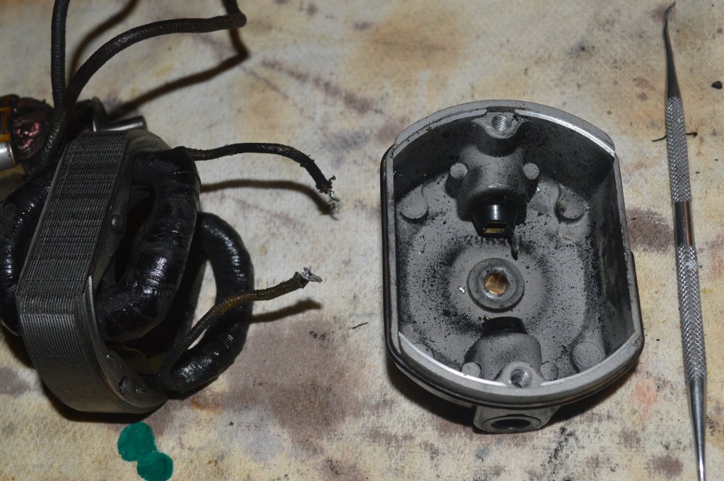
Moving on if you want to, the wires are de-soldered and the rear cap removed.
After de-soldering, the brush tubes can be removed. Each tube is held by a small set screw perpendicular to the brush tube that is loosened to remove the tubes. The tubes are removed from the inside out.
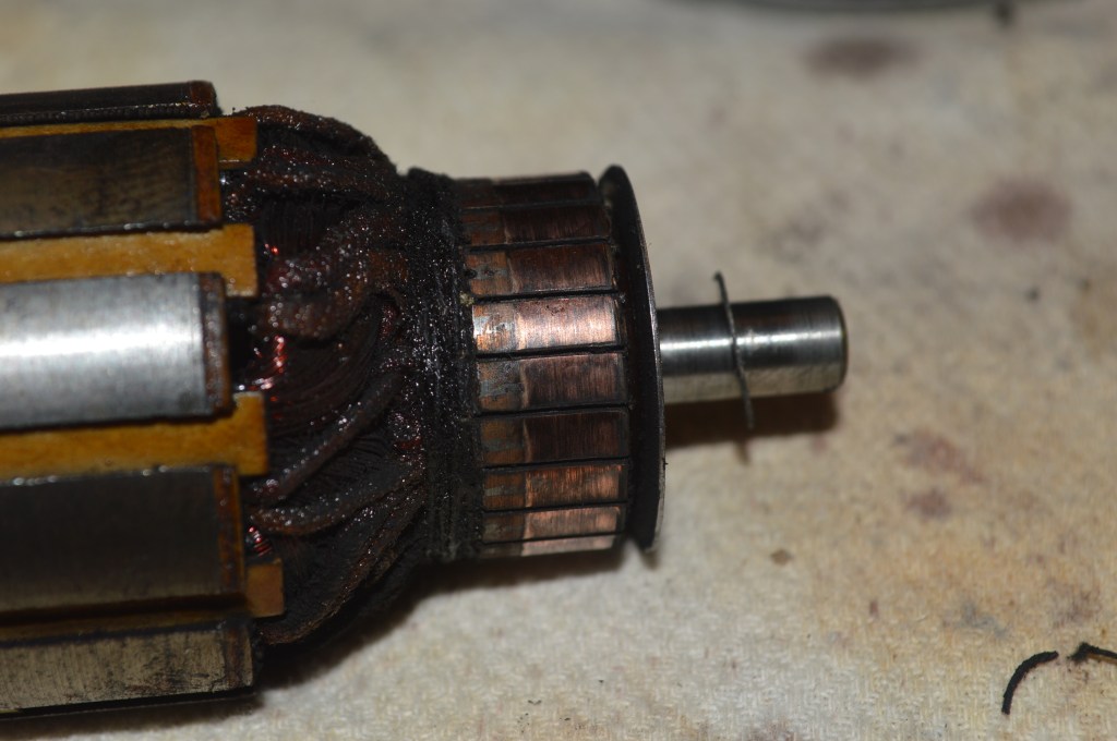
The end goal of a motor restoration is to restore performance. There are really 2 critical steps to achieve this (hence you don’t need to take all of the steps I do). The first is to polish the commutator (the round copper striped piece on the end of the commutator that the brushes ride on). It is found on the short shaft end of the armature. This restores good conductivity and a smooth surface for the brushes to rub against. I use a Dremel tool with jewelers rouge to restore and polish the surface. Before polishing…
After polishing…
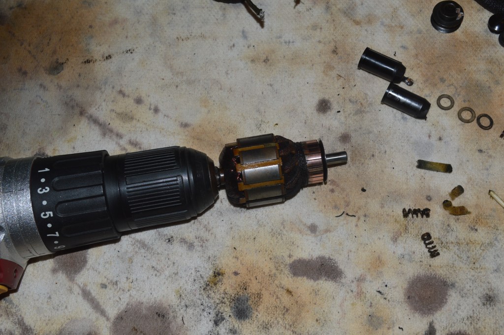
Then each end of the armature shaft is chucked in a drill and the shafts are polished with 1500 grit sand paper wetted with a light coat of oil.
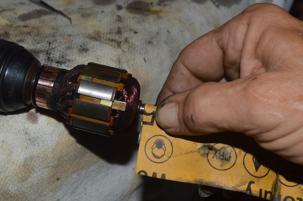
Don’t have a Dremel tool with buffing wheels and jewelers rouge? No problem, the commutator can be polished in a drill with 2500 grit sandpaper wetted with a SMALL amount of sewing machine oil. With one end of the shaft, wrap the paper around the commutator and using the drill to spin the commutator, gently and with light pressure, polish the commutator. Word of caution here, only polish as much as you need to… less is best. The copper is soft and can easily be removed TOO MUCH. When you are done, wipe of any remaining oil. The following picture shows this step for demonstration purposes.
Don’t have a drill? Well, you need a drill… DO NOT attempt to polish the commutator by hand. It must remain round. Cleaning without a drill will inevitably result in flat spots and an uneven wavy surface.
DO NOT attempt to do any cleaning of the armature with ANY chemical. Leave it alone. The wires you see tightly wrapped around the body of the armature are thin copper wires coated with lacquer. This is why they can be wrapped around and touch each other. Alcohol, acetone, and probably a million other cleaners can dissolve this THIN coating… if that happens, the motor wires will short out, and you will have a dead motor that will never run again. Actually, sometimes this is symptomatic of a motor that turns slowly and does not make any power… a new motor is the only fix for these. But that’s not the case here. The armature is set aside for reassembly.
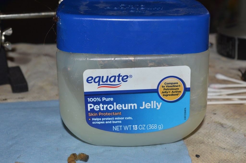
The second critical step is to address the grease wicks and restore proper lubrication to the motor. These motors are unique in that they have a round felt wick inside of a spring loaded grease tube. As the motor heats up, the grease melts, travels through the wick, and the spring pushes the felt against the motor shaft. Unfortunately, often times, the grease wick will freeze in the grease tube, and resist the spring enough that it no longer rubs against the shaft, and the lubrication is lost. Use 100% petroleum jelly for lubricant. It melts at the proper temperature and I am unaware of any commercially available grease formulation that works for these motors. You may debate the wisdom of this, but there is much on the topic to be found regarding the subject of compatible grease, and I have read in both Singer and White’s sewing machine literature that states it is acceptable to use petroleum jelly for these motors. Also, any reference I make to “grease” in this tutorial means “petroleum jelly”. I may use the terms interchangeably simply because that’s how my brain works.
In this tutorial, I am going to replace the grease wicks, but I would not recommend that you do this step. It is difficult to do and requires a new grease wick… which you do not have. The old grease wicks will almost assuredly be damaged in removal, and there is little hope you will be able to remove them in one piece, and then reinstall them. I will instead show you them removed, and explain how you can restore the function of your old grease wicks by freeing them up so they once again rub against the shaft with the spring pressure as they were designed to do. Keep it simple and be satisfied servicing them in place.
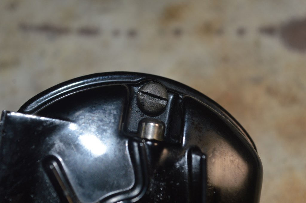
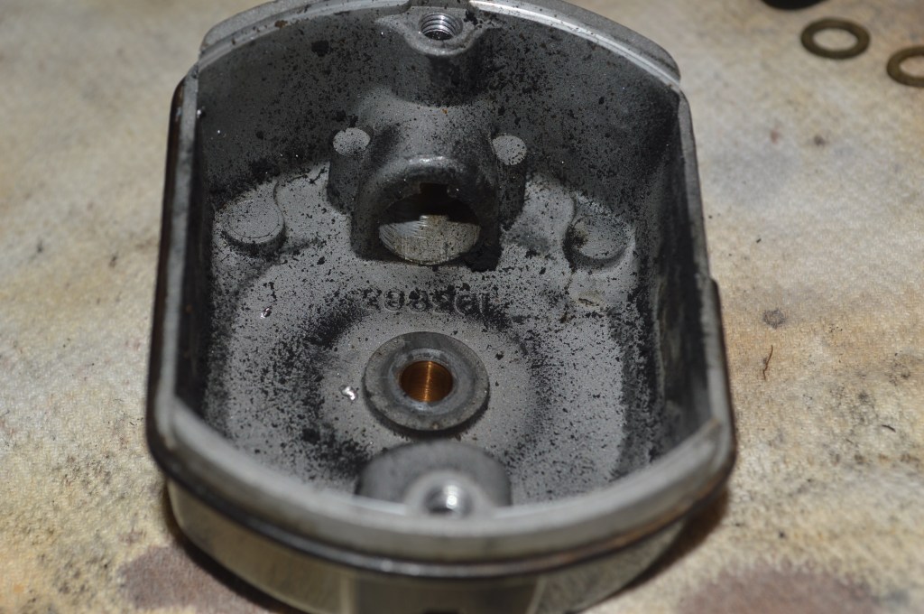
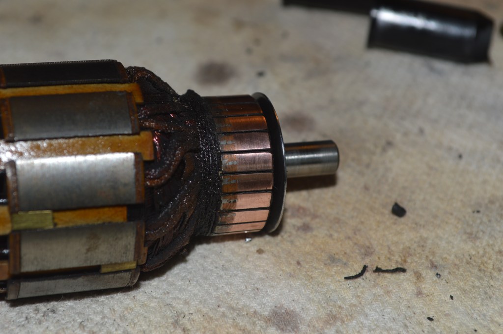
With the end cap removed, you should see the grease wick poking up into the bearing… it should look like this (it didn’t until I pushed it down).
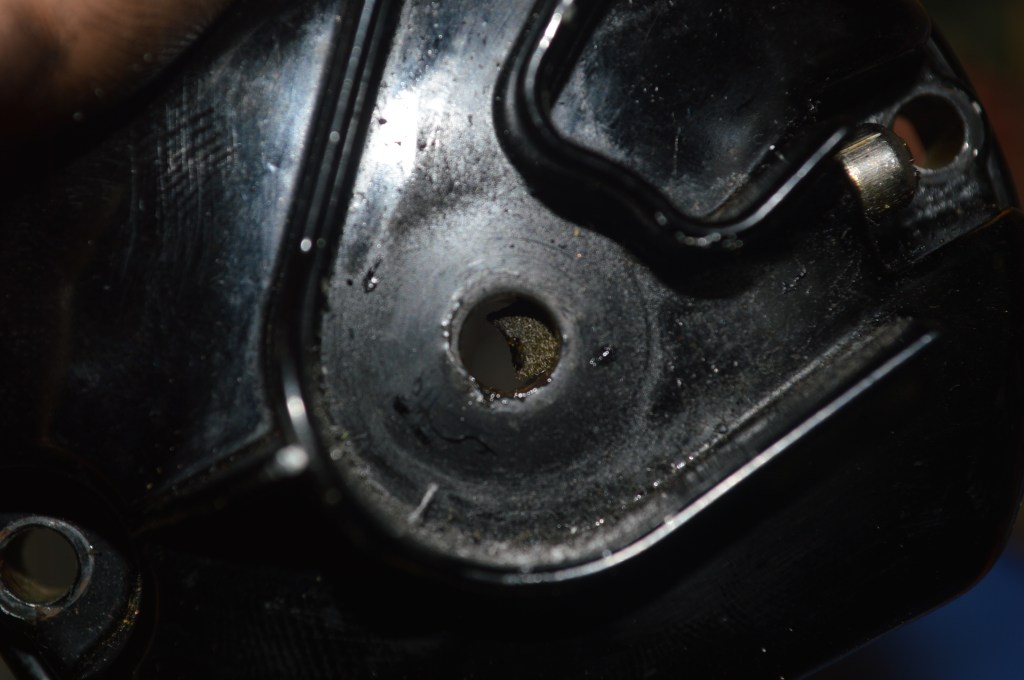
Most of the time it looks like this, the grease wick is frozen in the grease tube…
The grease wicks are removed by pushing a dentil pick (or a round tooth pick) into the top of the grease wick tube. Gently pushing on the wick will pop it into the bearing bore. Working from both sides, through the bearing, I “snake” it out of the grease wick tube. Further probing the inside walls of the grease tube, the spring is removed in similar fashion. Here are the grease wicks and springs removed from the motor.
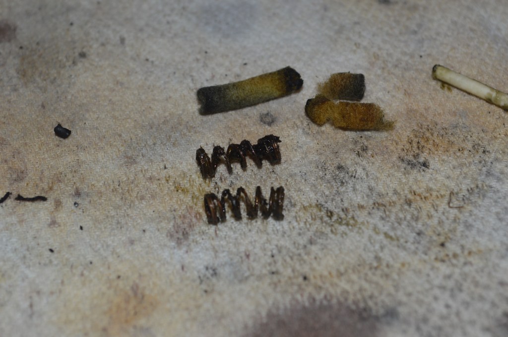
One of the grease wicks was destroyed in removal. These wicks are dry and brittle… It may be the cause of the noise due to the lack of a lubricating film.
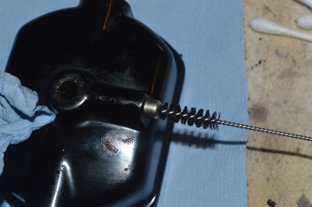
Here’s how to get the wicks working again without removing them. Using a dentil pick (or round tooth pick), push the wick into the bearing. Now, push it back up. Repeat this process until the grease wick will pop down under spring pressure each time you push it up. A small amount of petroleum jelly on the side of the wicks can help free them up to move in the tubes. While the wick is still not properly lubricated, there is enough lubrication applied in reinstalling the shafts for the motor to heat up, melt the petroleum jelly, and transport it to the shaft for proper lubrication. You may notice bubbles coming from the top of the grease wick tubes when you first use the restored motor. This is caused by the wicks absorbing the liquified grease and releasing air. This is a normal part of the break in of the motor and you will need to replenish the grease in the tubes regularly over time until the wick is saturated and the air bubbles cease. For my restoration, I remove the wicks, clean the springs, and remove all old grease from the grease tubes. The grease tubes are cleaned with kerosene, a carburetor brush, and compressed air.
The new wicks are cut to length, and charged with petroleum jelly by soaking them in petroleum jelly that has been melted. Note… Use 100% petroleum jelly… not scented or infused with any extract.
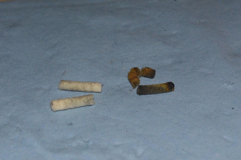
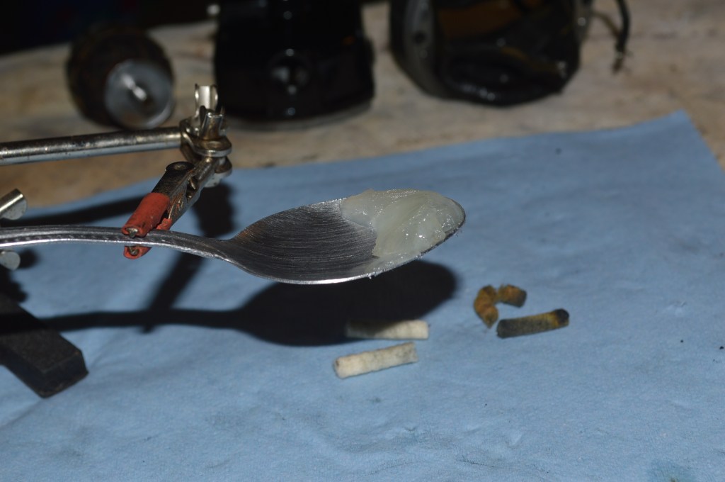
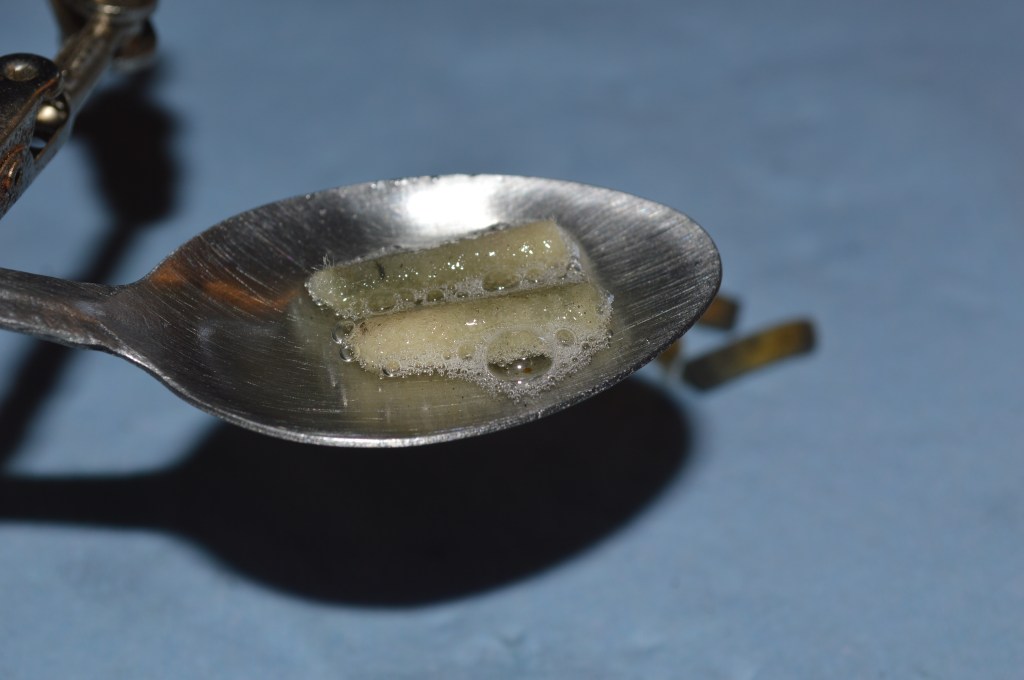
You can see the wicks bubble as they absorb the lubricant.
The springs and new grease wicks are installed in the opposite of their removal… it is a pain and difficult to snake these things back into the tube, and this step is not shown (it takes 2 hands and practice to do this successfully).
The next step of the restoration is reconditioning the brushes. This step is optional, but I do it because it makes sense with the level of restoration I do. I recommend you do it too. It’s a simple process to restore a flat surface on the end of the brush.
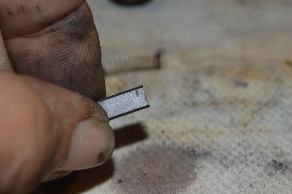
In normal wear, the brushes will contour to the curvature of the commutator. Flattening the face restores them to the profile they had when new. This provides a new wear surface for the commutator and reduced friction (less contact area) for the brushes. The next picture shows the curvature caused by normal wear (pardon my greasy finger… I was knuckle deep in grease tubes in the previous paragraphs!!
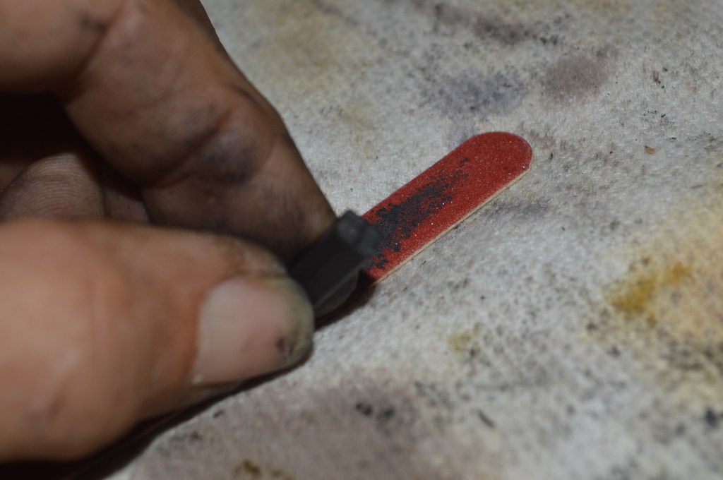
The brushes are made of graphite (good old time vintage pencil lead) and are easy to sand square with a piece of sandpaper or emery board.
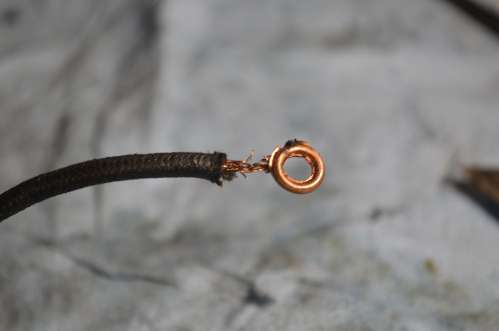
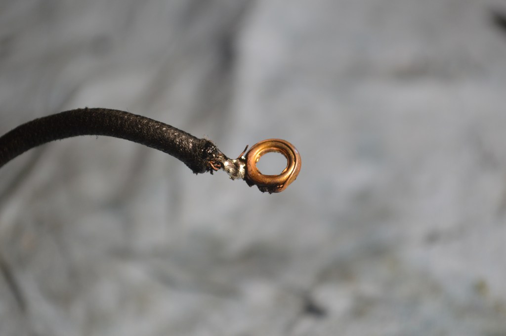
Everything is done and the motor is ready to reassemble. Prior to reassembling the pieces, the brush tubes are reinstalled and the brush wires re-soldered to the terminals. The only concern I had with the original wires was one connector had “thinned” wires. Some of the wire strands had broken. This is restored by bunching the wires and re-soldering the connector… good as new!
Although this motor does not need new wires, you may not be so lucky. The next step is to show you how to replace these wires. For this you will need a soldering iron, solder, 2 butt connectors, a wire stripping tool, 18 gauge stranded wire, and some shrink tubing. All of this is available at any good hardware store. A word about soldering irons… they are not all created equal. you want the iron to get hot enough that it will heat the joint quickly to melt the solder. The longer it takes, the hotter the wire you are soldering gets. The faster you can melt the solder, the better. You need a minimum of 30 watts… 40 watts is better.
Start by cutting the wire about 2 inches from the field coil. Next, strip the wire about 1/4″ and twist the strands tightly together. put the stripped end into a butt connector. Cut a liberal amount of 18 Gauge wire (several inches longer than the piece you cut). Strip about 1/4″ off of the wire, twist the strands and insert it into the butt connector. Using the stripping tool, gently crimp the butt connector enough to grip the wire, but not enough to squash it flat.
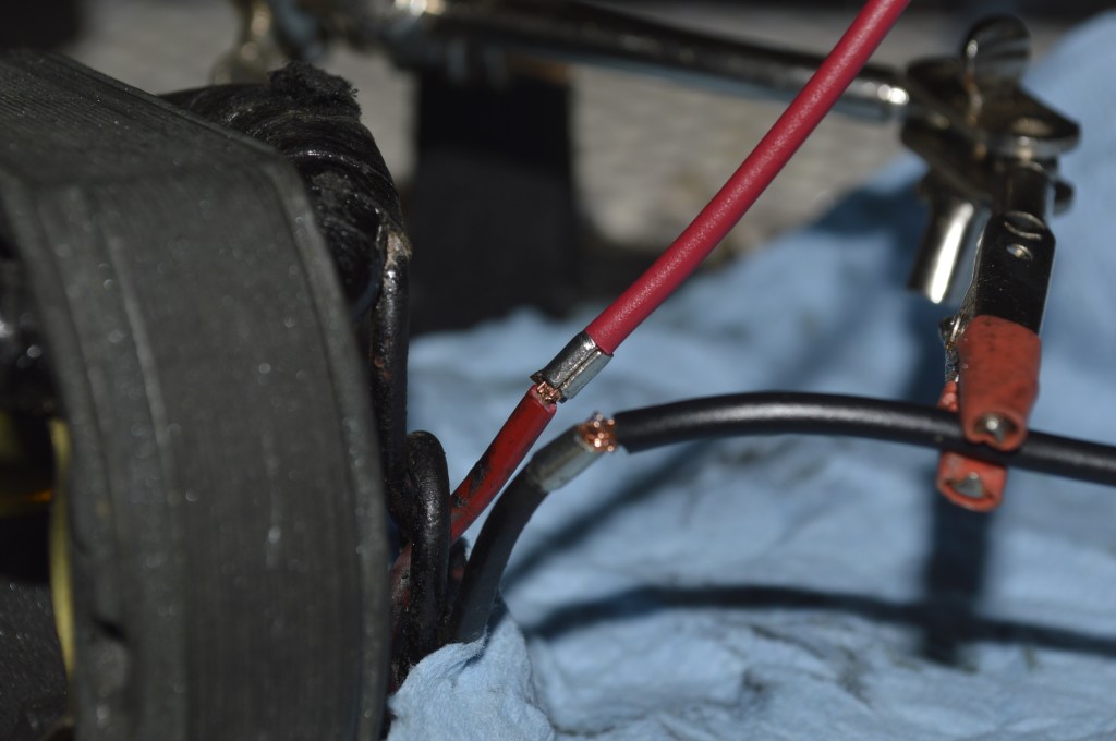
Heating the connector with the soldering iron, apply solder until it flows into the connector.
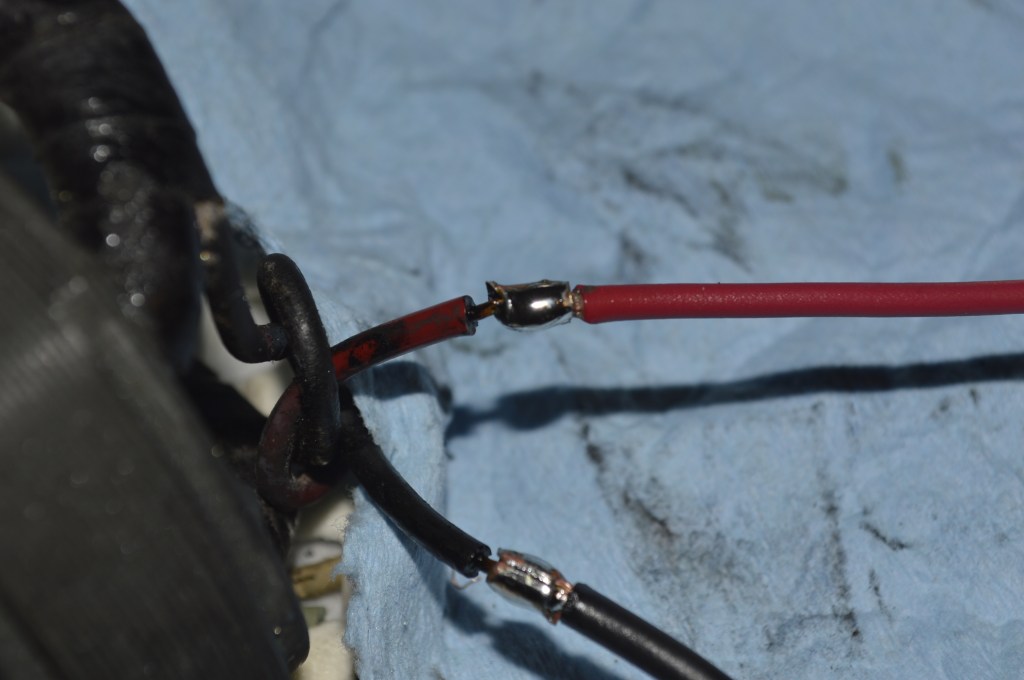
After the joint cools, slide a piece of shrink tubing slightly longer than the soldered joint, and heat with a butane lighter to shrink it tight around the soldered joint.
When you reassemble and mount the motor to your machine, you can determine the final length and cut the wire. Leave 1/4″ to strip, and reuse the connectors from the old wire. Solder the connectors to the new wire and insulate the joint with shrink tubing… so, that covers that.
Now it is time to reassemble the motor. Starting with the end cap (the one with brush tubes), refer to the pictures you took disassembling the motor to make sure you have the orientation correct. Press the field coil firmly to against the cap. You may notice that it fits and holds itself in place. Looking down into the field coil, make sure the brush tube wires are tucked under and out of the way to provide clearance for the commutator.
Next, install the armature, short shaft down (with the correct washers on the shaft). Apply a thin film of grease to the shaft and set it gently into the end cap bearing until it contacts the grease wick BUT NO MORE… remember you have a grease wick poking through and if you push the armature in too hard it will cut the grease wick as easily as a pair of scissors would. Hold the motor in your dominant hand, and with a round toothpick, press the wick up into the grease tube, now gently push the armature shaft full into the end cap. Rotate the armature by hand to make sure it is not rubbing against the brush tube wires. Now is the time to put the decorative cover back over the field coil, again making sure the orientation is correct.
Reinstalling the front cap is pretty much the same, but you need to start by pushing the wires through the grommet. Again, make sure the orientation is correct. Apply a thin film of grease to the armature shaft and only push enough to allow you to line up and start the long end of the armature shaft into the end cap bearing. Pop the wick up into the grease tube as before, and push the armature shaft to the outside edge of the bearing. Gently pull the wires to remove the slack that developed when toy seated the shaft into the bearing.
As you are pushing the end cap down, gently pull the slack out of the wires. Move slowly and repeat this over several iterations of pushing down the end cap and pulling the wires… remember, you don’t want to pull the wires too hard, and they are not flexible enough to pull after the end cap is seated. Once the cap is seated, give the wires one final tug to make sure there is no slack remaining. Failure to do this may cause the armature windings to rub against the wires, and a shorted motor will result.
Looking down the bolt holes in the front cap, make sure the holes align for the case screws to pass through. If the are misaligned, gently twist the motor casing to line them up. Insert the motor housing screws and tighten snugly. Turn the armature shaft by hand to make sure it is not hitting anything. It may feel a little stiff to turn, but not dragging against the wire.
Re-install the brushes into the brush tube and screw the brush caps on (do not tighten them too much. you can tighten them with your fingernail).
Push the pully onto the shaft, making sure the set screw is facing out and that it will tighten against the flat on the shaft.
Reinstall the motor and let it run! At first, you may notice that it runs slower that it did before you started, but as it settles in, it will increase in speed. This is normal and the motor needs to “break in” to it’s new condition. You will notice the increase in power right away. Running the motor a few minutes will settle everything in and warm the motor enough for the wicks to start absorbing grease.
If all went well, you should notice that your motor has more power, and runs smoothly. You might hear a slight “whirring” sound, but this is normal as the brushes break in with the motor… anyway, there is nothing left but to sew… and sew… and sew. The more you use these motors, the better they run, so don’t let your machine rest too long!
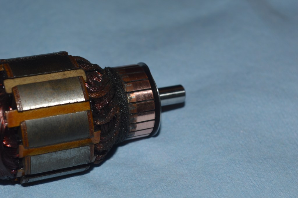
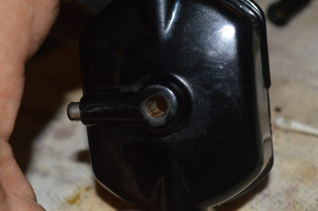
Oh, I almost forgot… here is the motor after restoration… looks just like it did when we started, but now we know it is in as good a shape on the inside as it is on the outside!
That’s it! The motor restoration is complete and it should run great for a long time.
I hope you found this information useful!
Please feel free to visit our Etsy store “Pungoliving” to see our fine quality restored vintage sewing machines and the work we do to restore them. They all have links to their respective restoration blog, or follow the link below:
https://www.etsy.com/shop/pungoliving
As always, our tutorials are provided as a free resource to help you learn and maintain your vintage sewing machine. As our site has grown, so has the cost to keep and maintain it. Despite these cost, I will strive to continue posting tutorials and other relevant content for the benefit of the sewing community. If you found the content of this tutorial useful, please consider making a small donation to help me grow the site and help defray my costs… every little bit helps.
Help Support our Site…
Make a one-time donation
Make a monthly donation
Make a yearly donation
Choose an amount
Or enter a custom amount
Your contribution is appreciated.
Your contribution is appreciated.
Your contribution is appreciated.
As always, if you have any questions or if I can be of any assistance in helping you with your sewing machine, feel free to send a message to pungoliving@gmail.com. I’ll be happy to assist you as best I can.
Thanks for reading!
Lee

Great tutorial thank you. I have my 222k motor disassembled but cannot slide armature free of the field coil. It seems like the edge of field coil is bent down/hangs into the space where the armature is. Any ideas how to remove? thanks
LikeLike
Hello Angie,
Sorry for the late reply… I came down with covid and it stopped me in my tracks. Just getting over it now!
The armature has a fan on the belt pully end. You need to remove the front motor cap and remove the armature from the front.
I hope this solved your problem!
Lee
LikeLike